Cirkit Designer
Your all-in-one circuit design IDE
Home /
Component Documentation
How to Use GND: Examples, Pinouts, and Specs

Introduction
The GND (Ground) is a fundamental component in electrical and electronic circuits. It serves as a reference point for measuring voltages and provides a common return path for electric current. Manufactured by SEAN with the part ID 09925676019, this component is essential for ensuring proper circuit operation and stability.
Explore Projects Built with GND
12V Multi-Component Control Circuit

This circuit appears to be a power distribution system that supplies power to various components from a 12V 5A power supply. It connects the negative terminal of the power supply to the ground (GND) pins of a mini diaphragm water pump, an RGB LED, a fan, and a water pump, while the positive DC output is connected to the positive pins of the RGB LED and presumably to other components through JST PH 2.0 connectors. The circuit lacks a controlling element, such as a microcontroller, suggesting that the components operate continuously or are switched externally.
Pushbutton Interface with General Purpose I/O Plug

This circuit consists of a General Purpose Input/Output (GPIO) plug connected to four pushbuttons. Each pushbutton is wired to a unique input pin on the GPIO plug, allowing the state of each button (pressed or not pressed) to be detected individually. The common terminals of the pushbuttons are interconnected and likely serve as a ground or reference voltage connection.
Basic Surge Protection Circuit with Benedict Switch

The circuit includes a Benedict Switch connected in series with a Fuse Holder and an SPD (Surge Protection Device). The SPD is also connected to a Ground reference. This configuration suggests that the circuit is designed to control power flow, protect against overcurrent with the fuse, and guard against voltage surges with the SPD, with a safe path to ground for surge dissipation.
Arduino UNO-Based Sensor Array with Resistor Network
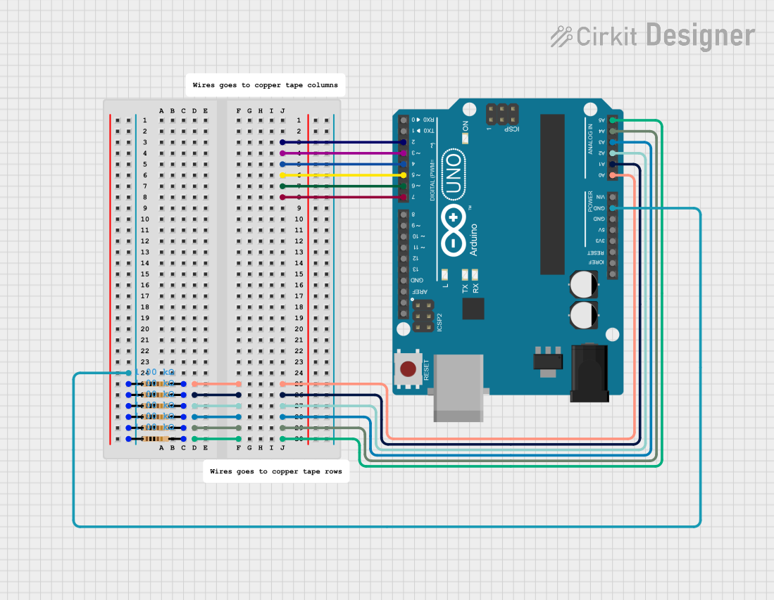
This circuit features an Arduino UNO microcontroller connected to six 1k Ohm resistors. Each resistor is connected between the ground (GND) and one of the analog input pins (A0 to A5) on the Arduino, likely for the purpose of reading analog sensor values or creating a voltage divider network.
Explore Projects Built with GND
12V Multi-Component Control Circuit
This circuit appears to be a power distribution system that supplies power to various components from a 12V 5A power supply. It connects the negative terminal of the power supply to the ground (GND) pins of a mini diaphragm water pump, an RGB LED, a fan, and a water pump, while the positive DC output is connected to the positive pins of the RGB LED and presumably to other components through JST PH 2.0 connectors. The circuit lacks a controlling element, such as a microcontroller, suggesting that the components operate continuously or are switched externally.
Pushbutton Interface with General Purpose I/O Plug
This circuit consists of a General Purpose Input/Output (GPIO) plug connected to four pushbuttons. Each pushbutton is wired to a unique input pin on the GPIO plug, allowing the state of each button (pressed or not pressed) to be detected individually. The common terminals of the pushbuttons are interconnected and likely serve as a ground or reference voltage connection.
Basic Surge Protection Circuit with Benedict Switch
The circuit includes a Benedict Switch connected in series with a Fuse Holder and an SPD (Surge Protection Device). The SPD is also connected to a Ground reference. This configuration suggests that the circuit is designed to control power flow, protect against overcurrent with the fuse, and guard against voltage surges with the SPD, with a safe path to ground for surge dissipation.
Arduino UNO-Based Sensor Array with Resistor Network
This circuit features an Arduino UNO microcontroller connected to six 1k Ohm resistors. Each resistor is connected between the ground (GND) and one of the analog input pins (A0 to A5) on the Arduino, likely for the purpose of reading analog sensor values or creating a voltage divider network.
Common Applications and Use Cases
- Used as a reference voltage in analog and digital circuits.
- Provides a return path for current in power supply systems.
- Ensures safety by grounding excess current in case of faults.
- Integral in PCB designs for signal integrity and noise reduction.
- Commonly used in microcontroller-based systems, such as Arduino projects.
Technical Specifications
Key Technical Details
- Manufacturer: SEAN
- Part ID: 09925676019
- Type: Electrical reference point
- Voltage: 0V (reference potential)
- Current Handling: Dependent on circuit design and trace width
- Material: Conductive (typically copper or other metals in PCB traces)
Pin Configuration and Descriptions
The GND component does not have a physical pin configuration in the traditional sense but is represented as a connection point in circuits. Below is an example of how GND is typically used in a circuit:
| Pin Name | Description | Connection |
|---|---|---|
| GND | Ground reference point | Connect to the negative terminal of the power supply or the common ground in the circuit. |
Usage Instructions
How to Use the Component in a Circuit
- Identify the Ground Point: In most circuits, the GND is represented by a symbol (⏚ or ⏚⏚) and is connected to the negative terminal of the power supply.
- Connect All Ground Points: Ensure that all components requiring a ground connection are linked to the GND node. This includes microcontrollers, sensors, and power supply units.
- Use a Ground Plane: For PCB designs, create a dedicated ground plane to reduce noise and improve signal integrity.
- Avoid Ground Loops: Ensure that there is only one common ground reference in the circuit to prevent unwanted current paths.
Important Considerations and Best Practices
- Trace Width: Ensure that the ground traces are wide enough to handle the expected current without significant voltage drop.
- Star Grounding: In complex circuits, use a star grounding technique to connect all ground points to a single node.
- Decoupling Capacitors: Place decoupling capacitors close to ICs to stabilize the voltage and reduce noise.
- Arduino Example: When using an Arduino UNO, connect the GND pin of the Arduino to the GND of the external circuit to ensure a common reference.
Example Arduino Code
Below is an example of how to use the GND connection in an Arduino circuit:
// Example: Blinking an LED with proper GND connection

int ledPin = 13; // Pin connected to the LED

void setup() {
  pinMode(ledPin, OUTPUT); // Set the LED pin as an output
}

void loop() {
  digitalWrite(ledPin, HIGH); // Turn the LED on
  delay(1000);                // Wait for 1 second
  digitalWrite(ledPin, LOW);  // Turn the LED off
  delay(1000);                // Wait for 1 second
}

// Note: Ensure the LED's cathode (shorter leg) is connected to GND
// and the anode (longer leg) is connected to the Arduino pin via a resistor.
Troubleshooting and FAQs
Common Issues Users Might Face
- Voltage Fluctuations: If the ground connection is not stable, voltage levels in the circuit may fluctuate.
- Solution: Check for loose connections or insufficient trace width in the PCB design.
- Ground Loops: Multiple ground points can create loops, leading to noise and interference.
- Solution: Use a single common ground reference and avoid connecting multiple ground points in a loop.
- Overheating: If the ground trace is too narrow, it may overheat due to excessive current.
- Solution: Increase the trace width or use a ground plane for better current handling.
Solutions and Tips for Troubleshooting
- Check Connections: Ensure all components are properly connected to the GND node.
- Use a Multimeter: Measure the voltage between the GND and other points in the circuit to verify proper operation.
- Inspect PCB Design: Review the PCB layout to ensure the ground plane is continuous and free of interruptions.
- Add Decoupling Capacitors: Place capacitors near power pins of ICs to stabilize the voltage and reduce noise.
By following these guidelines, the GND component (SEAN 09925676019) can be effectively used to ensure reliable and stable circuit operation.