
How to Use D31A Series Reed Relay: Examples, Pinouts, and Specs
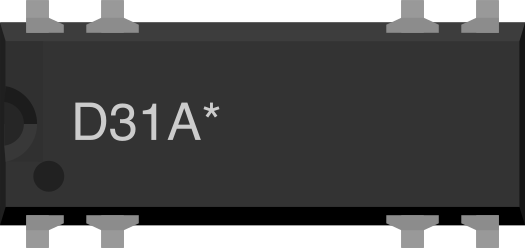
 Design with D31A Series Reed Relay in Cirkit Designer
Introduction
The D31A Series Reed Relay, manufactured by Celduc, is an electromagnetic switch that operates using a magnetic field to control a pair of contacts. This relay is renowned for its fast switching speed, low power consumption, and compact design. It is a reliable and efficient solution for applications requiring precise and rapid switching.
Explore Projects Built with D31A Series Reed Relay
 Open Project in Cirkit Designer
 Open Project in Cirkit Designer
 Open Project in Cirkit Designer
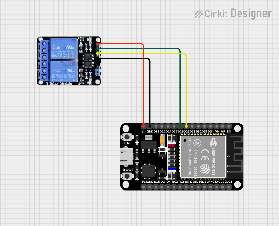 Open Project in Cirkit Designer
Explore Projects Built with D31A Series Reed Relay
Open Project in Cirkit DesignerOpen Project in Cirkit DesignerOpen Project in Cirkit DesignerOpen Project in Cirkit DesignerCommon Applications and Use Cases
- Automation Systems: Used in industrial automation for controlling actuators, sensors, and other devices.
- Telecommunications: Ideal for signal routing and switching in communication systems.
- Control Systems: Frequently employed in control panels and PLCs for managing electrical circuits.
- Test and Measurement Equipment: Used in precision testing setups due to its low contact resistance and high reliability.
Technical Specifications
The D31A Series Reed Relay is designed to meet the demands of modern electronic systems. Below are its key technical details:
General Specifications
| Parameter | Value |
|---|---|
| Contact Configuration | SPST (Single Pole Single Throw) |
| Switching Voltage (Max) | 200 V DC |
| Switching Current (Max) | 0.5 A |
| Contact Resistance | ≤ 150 mΩ |
| Coil Voltage Range | 5 V DC, 12 V DC, 24 V DC |
| Coil Resistance | Varies by model (e.g., 500 Ω for 12 V version) |
| Switching Speed | ≤ 0.5 ms (operate time) |
| Insulation Resistance | ≥ 10⁹ Ω |
| Operating Temperature | -40°C to +85°C |
| Dimensions | Compact, varies by model |
Pin Configuration and Descriptions
The D31A Series Reed Relay typically has four pins. The pinout is as follows:
| Pin Number | Name | Description |
|---|---|---|
| 1 | Coil (+) | Positive terminal of the relay coil |
| 2 | Coil (-) | Negative terminal of the relay coil |
| 3 | Common (COM) | Common terminal of the switch contact |
| 4 | Normally Open (NO) | Contact that closes when the relay is activated |
Usage Instructions
How to Use the D31A Series Reed Relay in a Circuit
- Power the Coil: Connect the coil terminals (Pin 1 and Pin 2) to a DC power source within the specified voltage range (e.g., 12 V DC for a 12 V relay).
- Control the Load: Connect the load circuit to the Common (COM) and Normally Open (NO) terminals. When the relay is activated, the NO contact will close, completing the circuit.
- Switching: Apply the appropriate voltage to the coil to activate the relay. The magnetic field generated will close the NO contact, allowing current to flow through the load.
Important Considerations and Best Practices
- Diode Protection: Always use a flyback diode across the coil terminals to protect the circuit from voltage spikes caused by the collapsing magnetic field when the relay is deactivated.
- Current Ratings: Ensure the load current does not exceed the relay's maximum switching current (0.5 A).
- Mounting: Secure the relay properly to avoid mechanical stress or vibration that could affect performance.
- Temperature Range: Operate the relay within the specified temperature range (-40°C to +85°C) to ensure reliability.
Example: Connecting to an Arduino UNO
The D31A Series Reed Relay can be easily controlled using an Arduino UNO. Below is an example circuit and code:
Circuit Setup
- Connect Pin 1 (Coil +) to a digital output pin on the Arduino (e.g., Pin 7) through a 1 kΩ resistor.
- Connect Pin 2 (Coil -) to the Arduino GND.
- Place a flyback diode (e.g., 1N4007) across the coil terminals, with the cathode connected to Pin 1.
- Connect the load circuit to Pin 3 (COM) and Pin 4 (NO).
Arduino Code
// D31A Series Reed Relay Control Example
// This code toggles the relay on and off every second.

const int relayPin = 7; // Pin connected to the relay coil (+) terminal

void setup() {
  pinMode(relayPin, OUTPUT); // Set relay pin as an output
}

void loop() {
  digitalWrite(relayPin, HIGH); // Activate the relay
  delay(1000); // Wait for 1 second
  digitalWrite(relayPin, LOW);  // Deactivate the relay
  delay(1000); // Wait for 1 second
}
Troubleshooting and FAQs
Common Issues and Solutions
Relay Not Activating
- Cause: Insufficient voltage or current to the coil.
- Solution: Verify the power supply voltage and ensure it matches the relay's coil voltage rating.
Load Circuit Not Switching
- Cause: Incorrect wiring of the load circuit.
- Solution: Double-check the connections to the COM and NO terminals.
Excessive Heat
- Cause: Overcurrent through the relay contacts or coil.
- Solution: Ensure the load current does not exceed 0.5 A and the coil voltage is within the specified range.
Noise or Chattering
- Cause: Unstable power supply or insufficient flyback diode protection.
- Solution: Use a stable power source and ensure a flyback diode is installed correctly.
FAQs
Q: Can the D31A Series Reed Relay switch AC loads?
A: Yes, it can switch low-power AC loads, but ensure the voltage and current ratings are not exceeded.
Q: What is the lifespan of the relay?
A: The relay has a mechanical lifespan of millions of operations, depending on the load and operating conditions.
Q: Can I use the relay for high-frequency switching?
A: Yes, the relay's fast switching speed (≤ 0.5 ms) makes it suitable for high-frequency applications, but ensure the load does not exceed the relay's ratings.
Q: Is the relay polarity-sensitive?
A: The coil terminals are polarity-sensitive, so ensure the correct polarity when connecting the power supply.