How to Use grove sound sensor: Examples, Pinouts, and Specs
Introduction
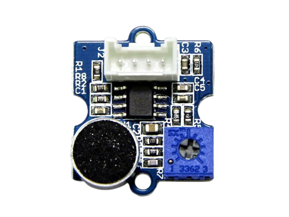
The Grove Sound Sensor is a compact and versatile module designed to detect sound levels and convert them into an electrical signal. It is based on a microphone and an amplifier circuit, making it suitable for sound detection and measurement in a variety of applications. This sensor is ideal for projects involving sound-activated systems, audio level monitoring, and environmental noise analysis.
Explore Projects Built with grove sound sensor
Explore Projects Built with grove sound sensor
Common Applications
- Sound-activated lighting systems
- Audio level monitoring
- Environmental noise detection
- Voice-activated projects
- Smart home automation
Technical Specifications
The following table outlines the key technical details of the Grove Sound Sensor:
| Parameter | Value |
|---|---|
| Operating Voltage | 3.3V to 5V |
| Output Signal | Analog (voltage proportional to sound level) |
| Sensitivity Range | 50Hz to 10kHz |
| Dimensions | 20mm x 20mm |
| Interface Type | Grove 4-pin interface |
| Operating Temperature | -40°C to 85°C |
Pin Configuration
The Grove Sound Sensor uses a 4-pin Grove connector. The pin configuration is as follows:
| Pin | Name | Description |
|---|---|---|
| 1 | VCC | Power supply pin (3.3V to 5V) |
| 2 | GND | Ground pin |
| 3 | SIG | Analog signal output (proportional to sound level) |
| 4 | NC | Not connected |
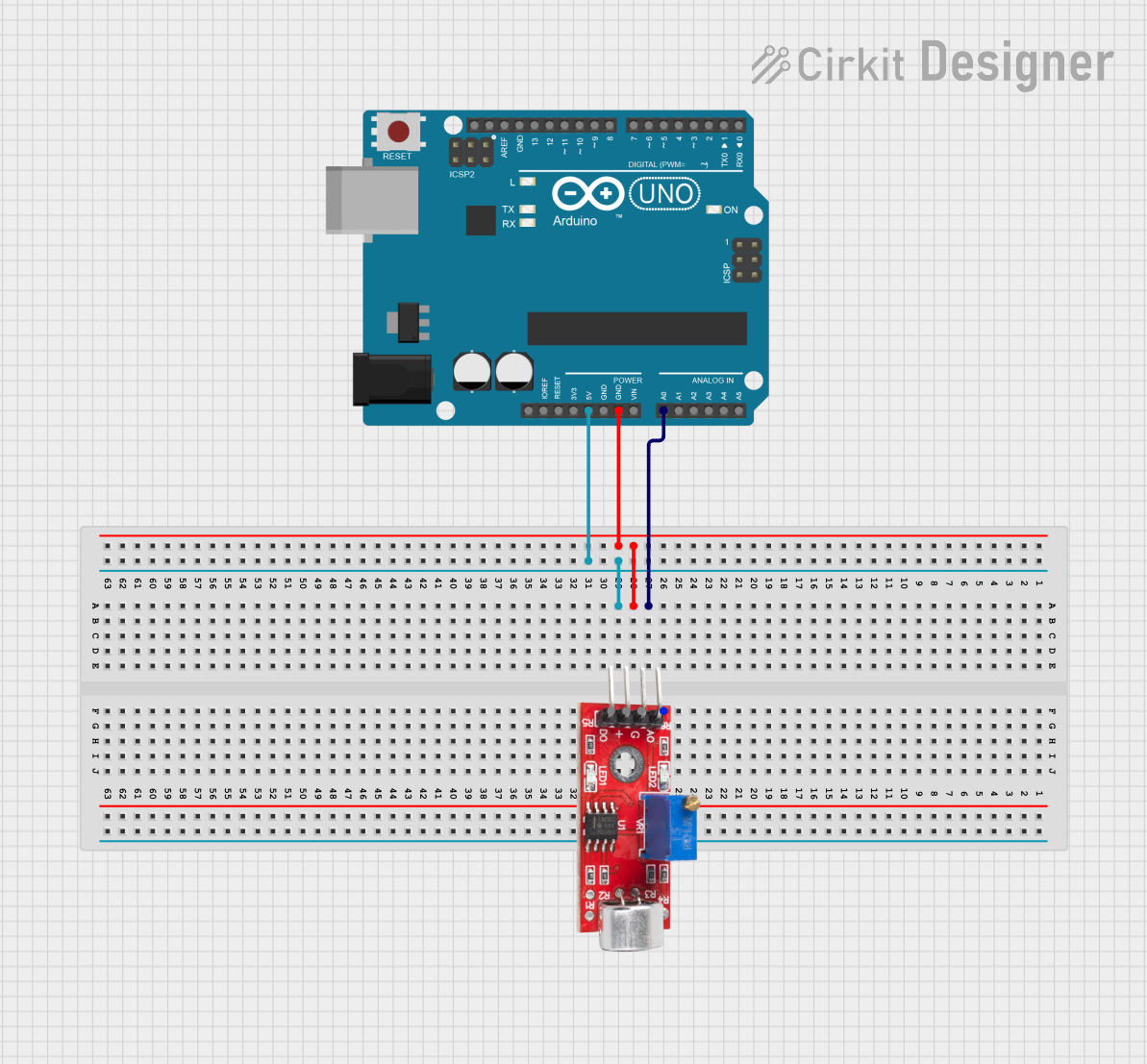
Usage Instructions
Connecting the Grove Sound Sensor
- Connect the Grove Sound Sensor to a Grove Base Shield or directly to an Arduino UNO using the Grove cable.
- Plug the sensor into an analog input port (e.g., A0) on the Base Shield.
- Ensure the Arduino is powered via USB or an external power source.
Sample Arduino Code
Below is an example of how to use the Grove Sound Sensor with an Arduino UNO to read and display sound levels:
// Include necessary libraries (if any additional libraries are required)
// Connect the Grove Sound Sensor to an analog pin (e.g., A0)

const int soundSensorPin = A0; // Define the analog pin connected to the sensor
int soundLevel = 0;            // Variable to store the sound level reading

void setup() {
  Serial.begin(9600); // Initialize serial communication at 9600 baud
  pinMode(soundSensorPin, INPUT); // Set the sensor pin as input
}

void loop() {
  soundLevel = analogRead(soundSensorPin); // Read the analog value from the sensor
  Serial.print("Sound Level: ");           // Print a label for the sound level
  Serial.println(soundLevel);              // Print the sound level value
  delay(500);                              // Wait for 500ms before the next reading
}
Important Considerations
- Power Supply: Ensure the sensor is powered within its operating voltage range (3.3V to 5V).
- Noise Sensitivity: The sensor is sensitive to environmental noise. Place it in a stable environment for accurate readings.
- Signal Processing: The raw analog output may require additional filtering or processing for specific applications.
Troubleshooting and FAQs
Common Issues
No Output or Incorrect Readings
- Cause: Improper connection or insufficient power supply.
- Solution: Verify the Grove cable connections and ensure the sensor is powered correctly.
Fluctuating or Unstable Readings
- Cause: Environmental noise or electrical interference.
- Solution: Place the sensor in a quieter environment or use a decoupling capacitor to reduce noise.
Low Sensitivity
- Cause: The sound source is too far or too quiet.
- Solution: Move the sound source closer to the sensor or increase the sound intensity.
FAQs
Q: Can the Grove Sound Sensor detect specific frequencies?
A: The sensor is designed to detect general sound levels within the range of 50Hz to 10kHz. It is not suitable for precise frequency analysis.
Q: How can I use the sensor for sound-activated control?
A: You can set a threshold value for the analog output and trigger an action (e.g., turning on an LED) when the sound level exceeds the threshold.
Q: Is the sensor compatible with Raspberry Pi?
A: Yes, the sensor can be used with Raspberry Pi via an analog-to-digital converter (ADC) since Raspberry Pi lacks native analog input pins.