How to Use Adafruit Adalogger FeatherWing: Examples, Pinouts, and Specs
Introduction
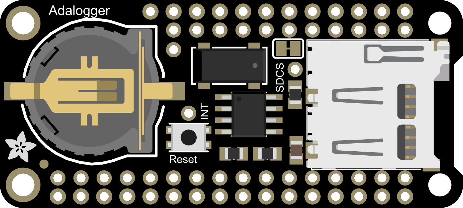
The Adafruit Adalogger FeatherWing is a compact, easy-to-use data logging module designed for a wide range of applications. It is particularly useful for projects that require the logging of sensor data over time, such as environmental monitoring, weather stations, or tracking system performance. With its onboard real-time clock (RTC) and SD card slot, the Adalogger FeatherWing provides accurate timestamping and large storage capacity for your data.
Explore Projects Built with Adafruit Adalogger FeatherWing

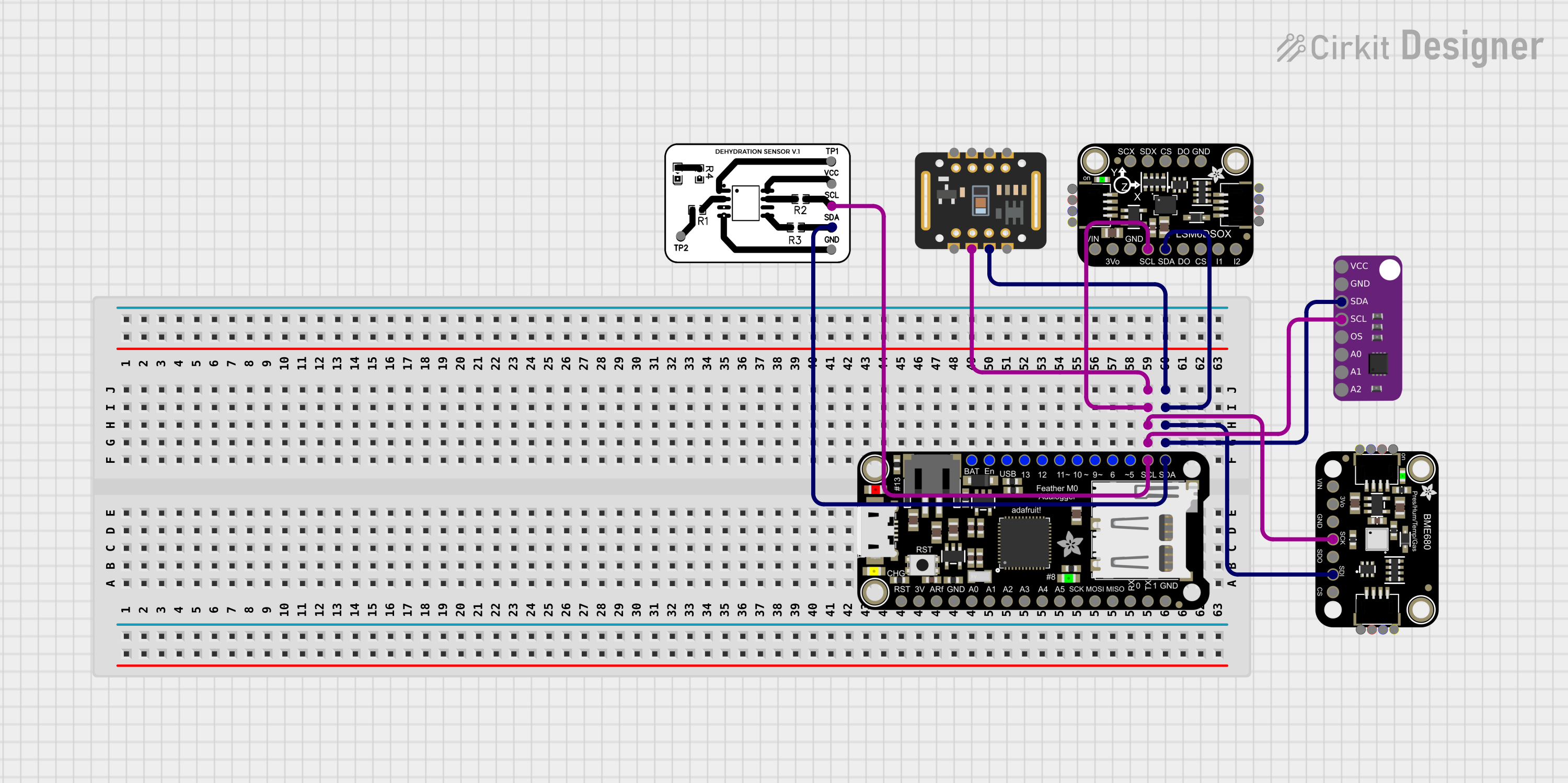
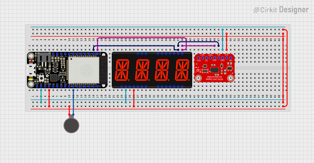
Explore Projects Built with Adafruit Adalogger FeatherWing
Technical Specifications
Key Features
- SD Card Slot: Supports standard and high capacity SD cards for data storage.
- Real-Time Clock (RTC): With a CR1220 coin cell battery (not included), the RTC keeps time even when the power is disconnected.
- I2C Interface: Allows for easy communication with a wide range of sensors and devices.
- Compatibility: Designed to work with Adafruit Feather boards but can be used with other microcontrollers via the I2C interface.
Electrical Characteristics
- Operating Voltage: 3.3V (from Feather board)
- Logic Level: 3.3V compatible
- Battery for RTC: CR1220 3V coin cell (not included)
Pin Configuration
| Pin Number | Description |
|---|---|
| 1 | GND (Ground) |
| 2 | 3V (3.3V power from Feather) |
| 3 | SCL (I2C clock) |
| 4 | SDA (I2C data) |
| 5 | #CS (Chip Select for SD) |
| 6 | SCK (SPI clock for SD) |
| 7 | MISO (SPI MISO for SD) |
| 8 | MOSI (SPI MOSI for SD) |
Usage Instructions
Connecting to a Feather Board
- Align the headers of the Adalogger FeatherWing with the corresponding pins on your Feather board.
- Solder the headers to ensure a secure and reliable connection.
- Insert a formatted SD card into the SD card slot.
- If using the RTC, insert a CR1220 coin cell battery into the battery holder.
Programming for Data Logging
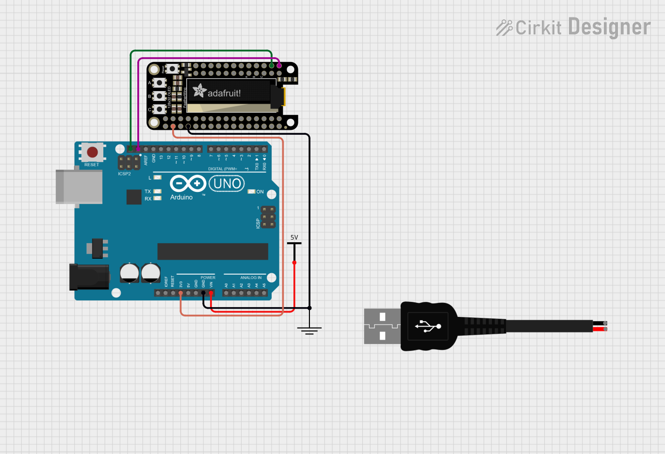
To use the Adalogger FeatherWing with an Arduino UNO, you will need to include the appropriate libraries for SD card and RTC functionality. Below is a sample code snippet that initializes both the SD card and RTC and writes a simple message with a timestamp to a file:
#include <SPI.h>
#include <SD.h>
#include <Wire.h>
#include <RTClib.h>

RTC_PCF8523 rtc; // Create an RTC object
File dataFile;

void setup() {
  Serial.begin(9600);

  // Initialize the RTC
  if (!rtc.begin()) {
    Serial.println("Couldn't find RTC");
    while (1);
  }

  // Initialize the SD card
  if (!SD.begin(5)) { // Chip Select pin for the SD card is 5
    Serial.println("Initialization failed!");
    return;
  }

  // Create or open the data file
  dataFile = SD.open("datalog.txt", FILE_WRITE);

  // Check if the file opened successfully
  if (!dataFile) {
    Serial.println("Error opening datalog.txt");
    return;
  }

  // Write a header for our data
  dataFile.println("Date,Time,Data");
}

void loop() {
  DateTime now = rtc.now(); // Get the current date and time
  dataFile.print(now.year(), DEC);
  dataFile.print('/');
  dataFile.print(now.month(), DEC);
  dataFile.print('/');
  dataFile.print(now.day(), DEC);
  dataFile.print(',');
  dataFile.print(now.hour(), DEC);
  dataFile.print(':');
  dataFile.print(now.minute(), DEC);
  dataFile.print(':');
  dataFile.print(now.second(), DEC);
  dataFile.print(',');

  // Replace this with actual sensor data
  dataFile.println("Sensor Data");

  dataFile.close(); // Close the file to save the data

  // Wait for 1 second before the next loop
  delay(1000);
}
Important Considerations and Best Practices
- Always safely eject the SD card from your computer before removing it.
- Ensure the RTC battery is installed correctly with the positive side facing up.
- Use a level shifter if you are interfacing with a 5V microcontroller to avoid damaging the 3.3V logic of the Adalogger FeatherWing.
Troubleshooting and FAQs
Common Issues
- SD Card Not Recognized: Ensure the SD card is formatted correctly (FAT32) and properly inserted into the slot.
- Incorrect Timestamps: Verify the RTC battery is installed and the RTC has been set with the correct time.
- Data Not Logging: Check the file opening and writing code for errors, and ensure the SD card has sufficient free space.
FAQs
Q: Can I use the Adalogger FeatherWing with a 5V microcontroller? A: Yes, but you will need to use a level shifter to convert the 5V signals to 3.3V to avoid damaging the board.
Q: How do I set the time on the RTC?
A: You can set the time on the RTC using the rtc.adjust(DateTime(__DATE__, __TIME__)); function in your setup code.
Q: What is the maximum size of SD card supported? A: The Adalogger FeatherWing supports SD cards up to 32GB formatted with the FAT32 file system.
For further assistance, consult the Adafruit forums or the detailed guides available on the Adafruit Learning System.