Cirkit Designer Logo
Cirkit Designer
Your all-in-one circuit design IDE
Home / 
Component Documentation

How to Use Buzzer: Examples, Pinouts, and Specs

Image of Buzzer
Cirkit Designer LogoDesign with Buzzer in Cirkit Designer

Introduction

A buzzer is an audio signaling device that produces sound when an electric current passes through it. It is widely used in various electronic applications to provide audible alerts or notifications. Buzzers are commonly found in alarms, timers, household appliances, and embedded systems. They are available in two main types: active buzzers, which generate sound when powered, and passive buzzers, which require an external signal to produce sound.

Explore Projects Built with Buzzer

Use Cirkit Designer to design, explore, and prototype these projects online. Some projects support real-time simulation. Click "Open Project" to start designing instantly!
Arduino UNO Controlled School Bell System with DS3231 RTC and Relay Module
Image of automatic bell system: A project utilizing Buzzer in a practical application
This circuit is designed as an automatic school bell system controlled by an Arduino UNO microcontroller. The Arduino is programmed to ring a buzzer at the start of each school period, with a total of 6 periods defined in the code. The DS3231 Real-Time Clock (RTC) module is used for accurate timekeeping, and a relay module interfaces the Arduino with the buzzer to handle the higher current required to drive the buzzer.
Cirkit Designer LogoOpen Project in Cirkit Designer
Battery-Powered IR Sensor and Buzzer Alarm System
Image of blindstick: A project utilizing Buzzer in a practical application
This circuit consists of an IR sensor and a buzzer powered by a 9V battery. The IR sensor detects an object and triggers the buzzer to sound an alarm when an object is detected.
Cirkit Designer LogoOpen Project in Cirkit Designer
Battery-Powered Buzzer Circuit
Image of  Buzzer with AA battery: A project utilizing Buzzer in a practical application
This circuit consists of a simple buzzer connected to a 3V battery source. The positive terminal of the battery is connected to the buzzer's power input, and the negative terminal is connected to the buzzer's ground. The circuit is designed to power the buzzer continuously, producing a constant sound or tone as long as the battery provides sufficient voltage.
Cirkit Designer LogoOpen Project in Cirkit Designer
Voice-Controlled Buzzer System with VC-02 Module
Image of vc: A project utilizing Buzzer in a practical application
This circuit features a VC-02 voice recognition module connected to a buzzer and powered by a 5V battery. The VC-02 module is programmed to listen for specific voice commands and, upon recognizing the command 'can you make a sound', it activates the buzzer for one second. The circuit is designed for voice-activated sound generation, with the VC-02 module handling voice recognition and serial communication, and the buzzer providing audible feedback.
Cirkit Designer LogoOpen Project in Cirkit Designer

Explore Projects Built with Buzzer

Use Cirkit Designer to design, explore, and prototype these projects online. Some projects support real-time simulation. Click "Open Project" to start designing instantly!
Image of automatic bell system: A project utilizing Buzzer in a practical application
Arduino UNO Controlled School Bell System with DS3231 RTC and Relay Module
This circuit is designed as an automatic school bell system controlled by an Arduino UNO microcontroller. The Arduino is programmed to ring a buzzer at the start of each school period, with a total of 6 periods defined in the code. The DS3231 Real-Time Clock (RTC) module is used for accurate timekeeping, and a relay module interfaces the Arduino with the buzzer to handle the higher current required to drive the buzzer.
Cirkit Designer LogoOpen Project in Cirkit Designer
Image of blindstick: A project utilizing Buzzer in a practical application
Battery-Powered IR Sensor and Buzzer Alarm System
This circuit consists of an IR sensor and a buzzer powered by a 9V battery. The IR sensor detects an object and triggers the buzzer to sound an alarm when an object is detected.
Cirkit Designer LogoOpen Project in Cirkit Designer
Image of  Buzzer with AA battery: A project utilizing Buzzer in a practical application
Battery-Powered Buzzer Circuit
This circuit consists of a simple buzzer connected to a 3V battery source. The positive terminal of the battery is connected to the buzzer's power input, and the negative terminal is connected to the buzzer's ground. The circuit is designed to power the buzzer continuously, producing a constant sound or tone as long as the battery provides sufficient voltage.
Cirkit Designer LogoOpen Project in Cirkit Designer
Image of vc: A project utilizing Buzzer in a practical application
Voice-Controlled Buzzer System with VC-02 Module
This circuit features a VC-02 voice recognition module connected to a buzzer and powered by a 5V battery. The VC-02 module is programmed to listen for specific voice commands and, upon recognizing the command 'can you make a sound', it activates the buzzer for one second. The circuit is designed for voice-activated sound generation, with the VC-02 module handling voice recognition and serial communication, and the buzzer providing audible feedback.
Cirkit Designer LogoOpen Project in Cirkit Designer

Technical Specifications

Below are the general technical specifications for a typical buzzer. Note that specific values may vary depending on the manufacturer and model.

General Specifications

  • Operating Voltage: 3V to 12V (commonly 5V)
  • Current Consumption: 10mA to 50mA
  • Sound Frequency: 2 kHz to 4 kHz (typical)
  • Sound Pressure Level (SPL): 85 dB to 100 dB at 10 cm
  • Type: Active or Passive
  • Operating Temperature: -20°C to 70°C

Pin Configuration and Descriptions

The buzzer typically has two pins, as described below:

Pin Name Description
1 Positive (+) Connect to the positive terminal of the power supply or control signal (e.g., 5V).
2 Negative (-) Connect to the ground (GND) of the circuit.

Note: For active buzzers, simply applying a voltage will produce sound. For passive buzzers, a PWM (Pulse Width Modulation) signal is required to generate sound.

Usage Instructions

How to Use the Buzzer in a Circuit

  1. Identify the Type of Buzzer: Determine whether the buzzer is active or passive. Active buzzers are easier to use as they only require a DC voltage, while passive buzzers need a PWM signal.
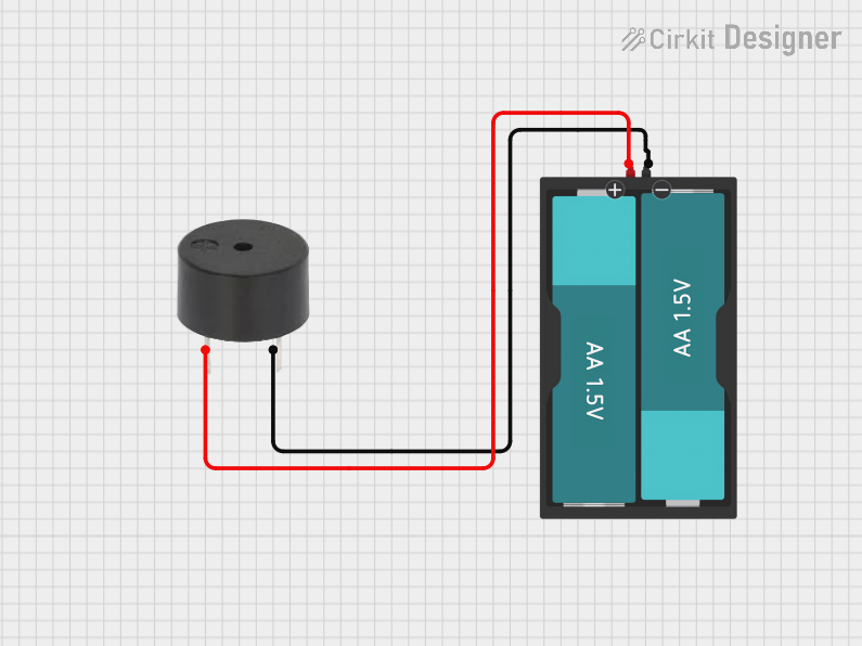
  2. Connect the Pins:
    • Connect the positive pin of the buzzer to the power supply or control signal (e.g., a microcontroller pin).
    • Connect the negative pin to the ground (GND) of the circuit.
  3. Power the Buzzer:
    • For an active buzzer, apply the appropriate voltage (e.g., 5V) to the positive pin to produce sound.
    • For a passive buzzer, generate a PWM signal from a microcontroller to drive the buzzer.

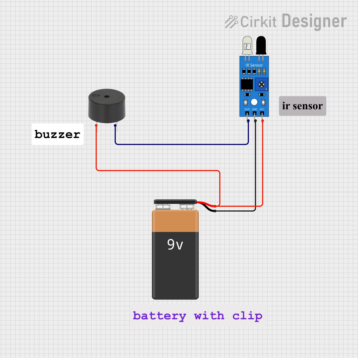
Example: Connecting a Buzzer to an Arduino UNO

Below is an example of how to connect and control a passive buzzer using an Arduino UNO.

Circuit Diagram

  • Connect the positive pin of the buzzer to Arduino digital pin 9.
  • Connect the negative pin of the buzzer to the GND pin of the Arduino.

Arduino Code

// Example code to control a passive buzzer with Arduino UNO
// This code generates a tone on the buzzer using the tone() function.

#define BUZZER_PIN 9  // Define the pin connected to the buzzer

void setup() {
  pinMode(BUZZER_PIN, OUTPUT);  // Set the buzzer pin as an output
}

void loop() {
  tone(BUZZER_PIN, 1000);  // Generate a 1 kHz tone on the buzzer
  delay(1000);             // Wait for 1 second
  noTone(BUZZER_PIN);      // Stop the tone
  delay(1000);             // Wait for 1 second
}

Important Considerations and Best Practices

  • Voltage Compatibility: Ensure the operating voltage of the buzzer matches the power supply or control signal.
  • Current Limitation: If the buzzer draws more current than the microcontroller pin can supply, use a transistor or MOSFET as a driver.
  • Sound Level: Place the buzzer in an open area for maximum sound output. Avoid obstructing the sound hole.
  • Type Selection: Use an active buzzer for simple applications and a passive buzzer for more control over sound frequency and patterns.

Troubleshooting and FAQs

Common Issues and Solutions

  1. No Sound from the Buzzer:

    • Cause: Incorrect wiring or insufficient voltage.
    • Solution: Verify the connections and ensure the power supply matches the buzzer's operating voltage.
  2. Low or Distorted Sound:

    • Cause: Insufficient current or obstructed sound hole.
    • Solution: Check the current supply and ensure the buzzer is not blocked.
  3. Buzzer Not Responding to PWM Signal:

    • Cause: Using an active buzzer instead of a passive one.
    • Solution: Confirm the type of buzzer and use a passive buzzer for PWM control.
  4. Overheating:

    • Cause: Exceeding the voltage or current rating.
    • Solution: Use a resistor or driver circuit to limit the current.

FAQs

  • Q: Can I use a buzzer with a 3.3V microcontroller?
    A: Yes, but ensure the buzzer operates at 3.3V. If not, use a transistor or MOSFET to drive the buzzer with a higher voltage.

  • Q: How do I generate different tones with a passive buzzer?
    A: Use the tone() function in Arduino to generate different frequencies, which correspond to different tones.

  • Q: Can I use a buzzer for continuous sound?
    A: Yes, for an active buzzer, simply apply a constant voltage. For a passive buzzer, generate a continuous PWM signal.

  • Q: What is the difference between active and passive buzzers?
    A: Active buzzers have an internal oscillator and produce sound when powered. Passive buzzers require an external signal to generate sound.