How to Use Relais BGK: Examples, Pinouts, and Specs
Introduction
The Relais BGK is an electromechanical switching device designed to control electrical circuits. It operates by using a coil that, when energized, either opens or closes its internal contacts, allowing or interrupting the flow of electricity. This component is widely used in applications where electrical isolation, high-current switching, or remote control of circuits is required.
Explore Projects Built with Relais BGK

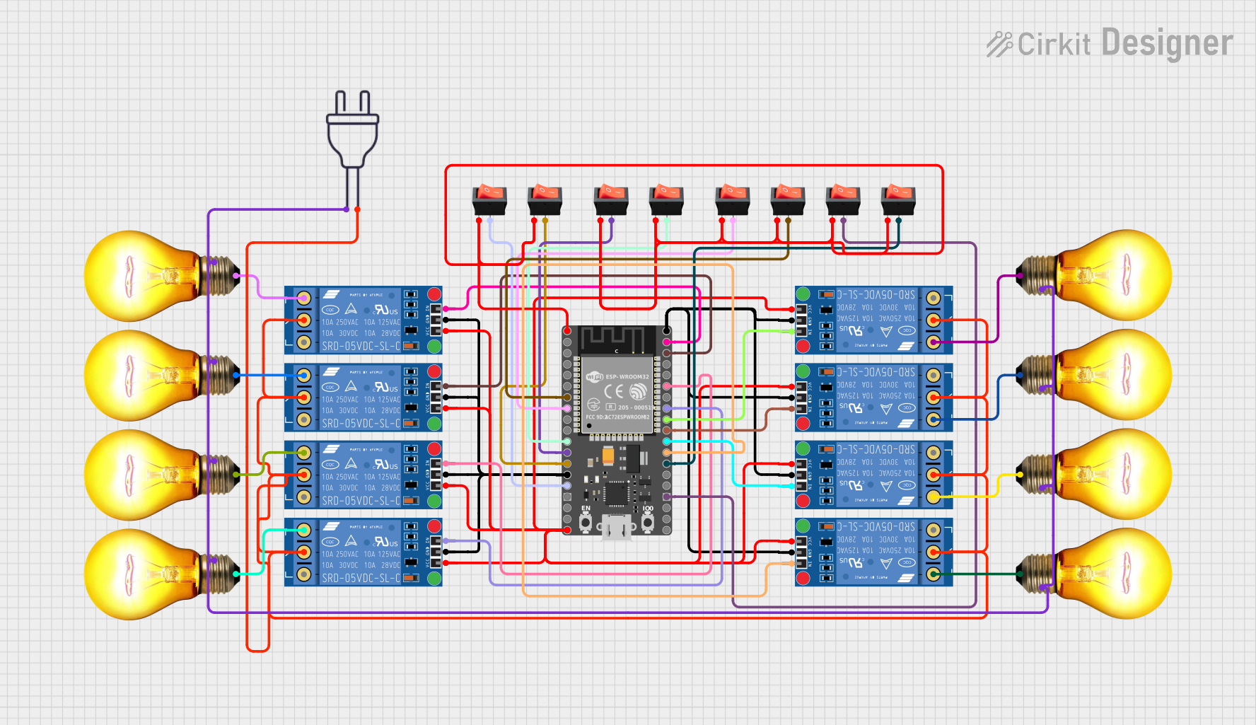
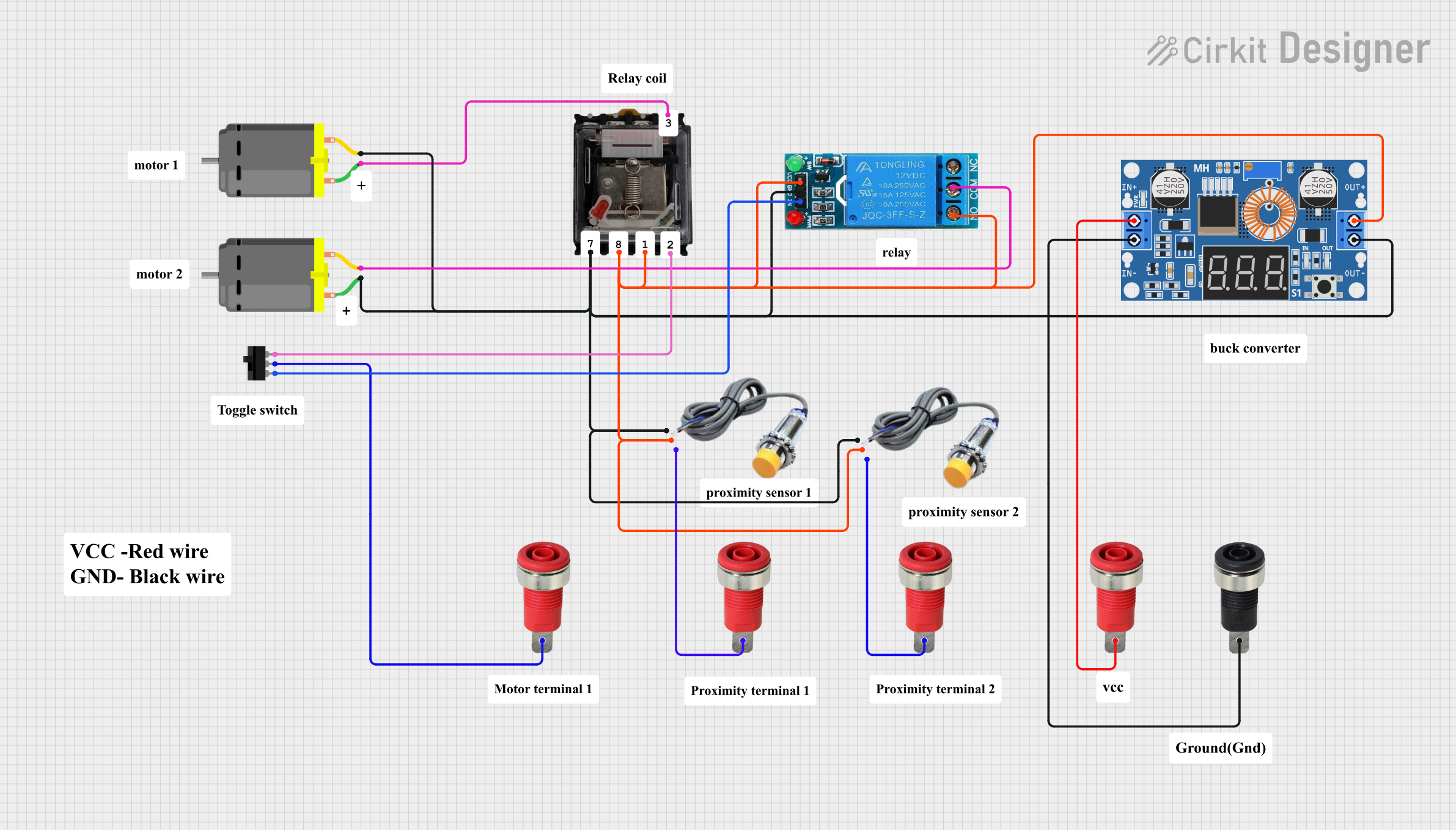

Explore Projects Built with Relais BGK
Common Applications and Use Cases
- Home automation systems
- Industrial control panels
- Motor control circuits
- Power distribution systems
- Automotive electronics
- Microcontroller-based projects (e.g., Arduino, Raspberry Pi)
Technical Specifications
Key Technical Details
- Coil Voltage: 5V DC, 12V DC, or 24V DC (depending on the model)
- Contact Rating: 10A at 250V AC or 10A at 30V DC
- Contact Configuration: SPDT (Single Pole Double Throw) or DPDT (Double Pole Double Throw)
- Coil Resistance: Varies by model (e.g., 70Ω for 5V version)
- Switching Time: Typically 10ms (operate) and 5ms (release)
- Dielectric Strength: 1500V AC between coil and contacts
- Insulation Resistance: ≥100MΩ at 500V DC
- Operating Temperature: -40°C to +85°C
- Mechanical Life: 10 million operations (minimum)
- Electrical Life: 100,000 operations (minimum)
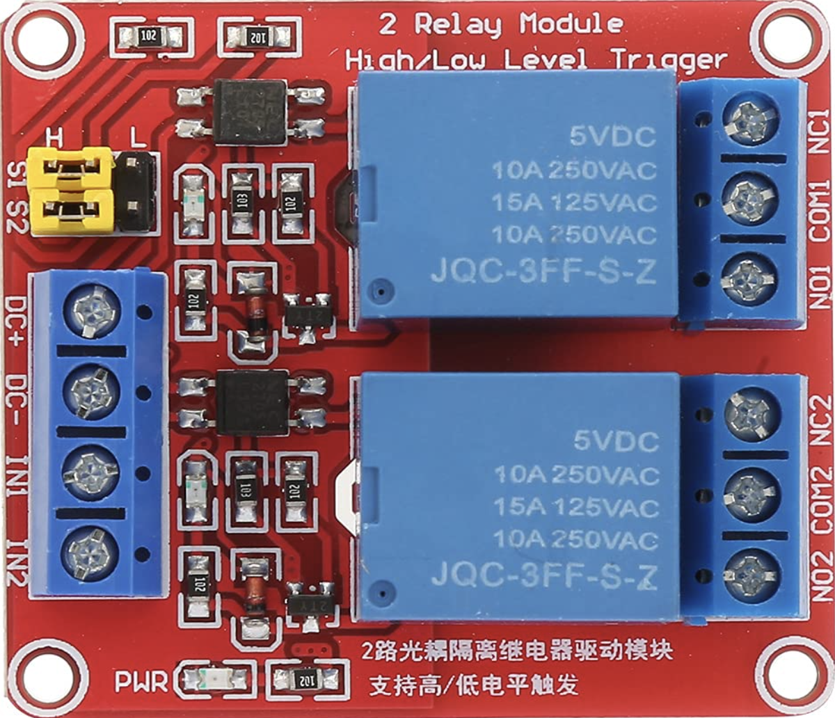
Pin Configuration and Descriptions
The Relais BGK typically has 5 or more pins, depending on the model. Below is a general pinout for a 5-pin SPDT relay:
| Pin Number | Name | Description |
|---|---|---|
| 1 | Coil (+) | Positive terminal of the relay coil. Connect to the control voltage source. |
| 2 | Coil (-) | Negative terminal of the relay coil. Connect to ground. |
| 3 | Common (COM) | Common terminal for the switching contacts. |
| 4 | Normally Open (NO) | Contact that remains open when the coil is not energized. Closes when energized. |
| 5 | Normally Closed (NC) | Contact that remains closed when the coil is not energized. Opens when energized. |
For DPDT relays, there will be additional pins for the second set of contacts.
Usage Instructions
How to Use the Relais BGK in a Circuit
- Power the Coil: Connect the coil pins (1 and 2) to a DC voltage source that matches the relay's rated coil voltage (e.g., 5V, 12V, or 24V). Use a transistor or MOSFET to control the coil if using a microcontroller.
- Connect the Load: Wire the load to the Common (COM) pin and either the Normally Open (NO) or Normally Closed (NC) pin, depending on the desired behavior:
- Use the NO pin if the load should be powered only when the relay is energized.
- Use the NC pin if the load should be powered when the relay is not energized.
- Add a Flyback Diode: Place a flyback diode (e.g., 1N4007) across the coil terminals to protect the circuit from voltage spikes when the relay is de-energized.
- Control the Relay: Use a microcontroller, switch, or other control circuit to energize the coil and switch the relay contacts.
Important Considerations and Best Practices
- Voltage Matching: Ensure the coil voltage matches the control voltage to avoid damaging the relay.
- Current Handling: Verify that the relay's contact rating is sufficient for the load's current and voltage.
- Isolation: Use optocouplers or isolation circuits when controlling the relay with sensitive electronics.
- Debouncing: Implement software or hardware debouncing to handle contact bounce during switching.
- Heat Dissipation: Avoid exceeding the relay's rated current to prevent overheating.
Example: Using Relais BGK with Arduino UNO
Below is an example of how to control a Relais BGK with an Arduino UNO:
// Define the pin connected to the relay module
const int relayPin = 7;

void setup() {
  // Set the relay pin as an output
  pinMode(relayPin, OUTPUT);

  // Ensure the relay is off at startup
  digitalWrite(relayPin, LOW);
}

void loop() {
  // Turn the relay on
  digitalWrite(relayPin, HIGH);
  delay(1000); // Keep the relay on for 1 second

  // Turn the relay off
  digitalWrite(relayPin, LOW);
  delay(1000); // Keep the relay off for 1 second
}
Note: When connecting the relay to the Arduino, use a relay module with built-in driver circuitry or add a transistor and flyback diode to safely drive the relay.
Troubleshooting and FAQs
Common Issues and Solutions
Relay Not Switching
- Cause: Insufficient coil voltage or current.
- Solution: Verify the control voltage and ensure it matches the relay's rated coil voltage. Check the power supply and connections.
Contact Bounce
- Cause: Mechanical nature of the relay contacts.
- Solution: Use a capacitor or software debouncing to smooth out the signal.
Overheating
- Cause: Exceeding the relay's current or voltage rating.
- Solution: Ensure the load does not exceed the relay's contact rating. Use a higher-rated relay if necessary.
Voltage Spikes Damaging Circuit
- Cause: Inductive kickback from the relay coil.
- Solution: Add a flyback diode across the coil terminals to suppress voltage spikes.
Relay Clicking but No Load Switching
- Cause: Incorrect wiring of the load or damaged contacts.
- Solution: Double-check the wiring and test the relay contacts with a multimeter.
FAQs
Q: Can I use the Relais BGK with AC loads?
A: Yes, the relay can switch AC loads, provided the voltage and current are within the contact rating.Q: How do I know if the relay is energized?
A: Many relay modules include an LED indicator that lights up when the coil is energized.Q: Can I control the relay directly from a microcontroller?
A: Not directly. Use a transistor or relay driver circuit to handle the current required by the relay coil.Q: What is the purpose of the flyback diode?
A: The flyback diode protects the control circuit from voltage spikes generated when the relay coil is de-energized.
By following this documentation, you can effectively integrate the Relais BGK into your projects and troubleshoot common issues.