How to Use Adafruit LSM6DSOX: Examples, Pinouts, and Specs
Introduction
The Adafruit LSM6DSOX is a state-of-the-art 6-DoF (Degrees of Freedom) sensor module that combines a digital 3-axis accelerometer and a 3-axis gyroscope into a single package. This sensor is designed for motion tracking in a wide range of applications, including gaming, virtual reality, inertial measurement units (IMUs), and fitness devices. Its small form factor and low power consumption make it ideal for portable electronics.
Explore Projects Built with Adafruit LSM6DSOX
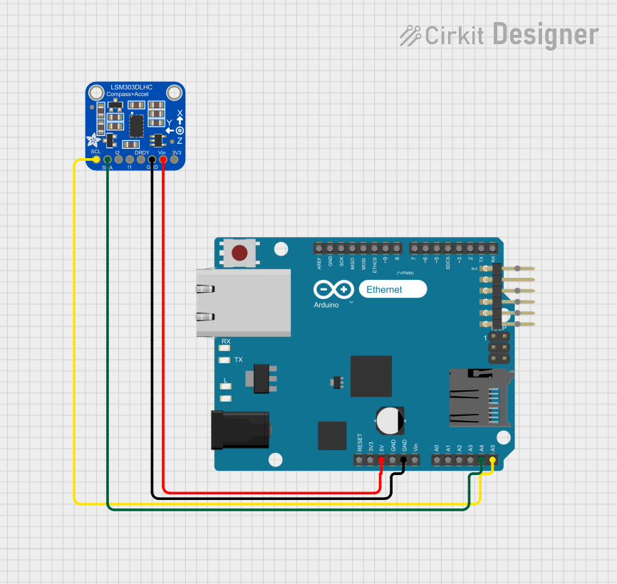
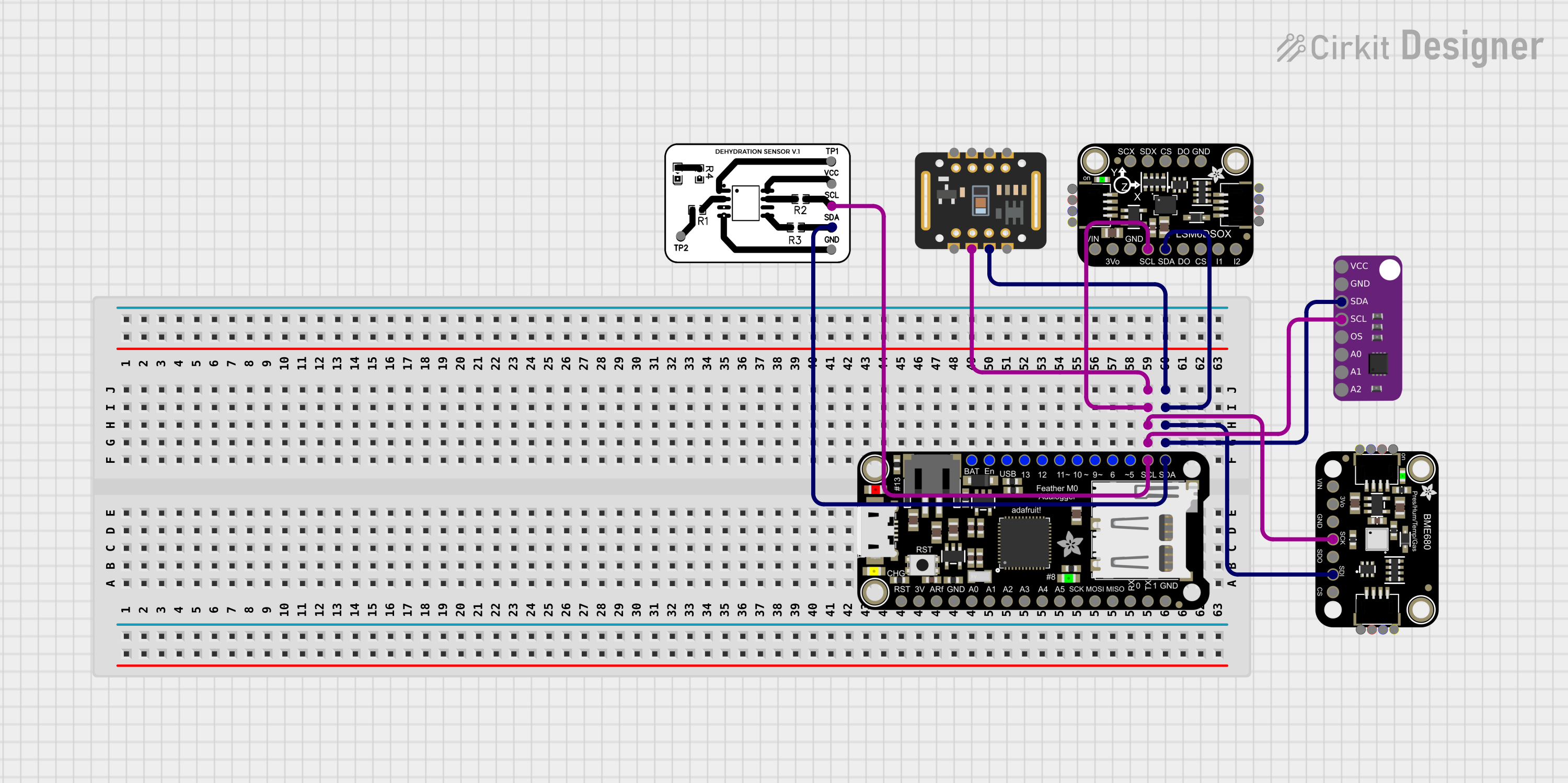

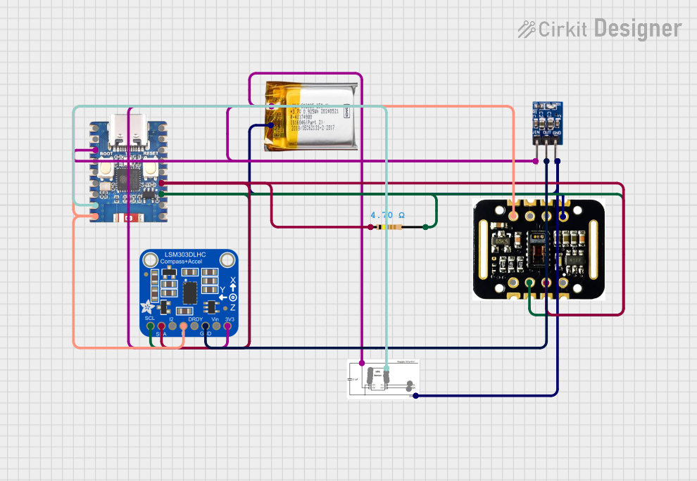
Explore Projects Built with Adafruit LSM6DSOX
Technical Specifications
Key Features
- Accelerometer Range: ±2/±4/±8/±16 g
- Gyroscope Range: ±125/±250/±500/±1000/±2000 dps (degrees per second)
- Communication: I2C and SPI interfaces
- Supply Voltage: 1.71 V to 3.6 V
- Operating Temperature: -40°C to 85°C
- Output Data Rates (ODR): up to 6.66 kHz
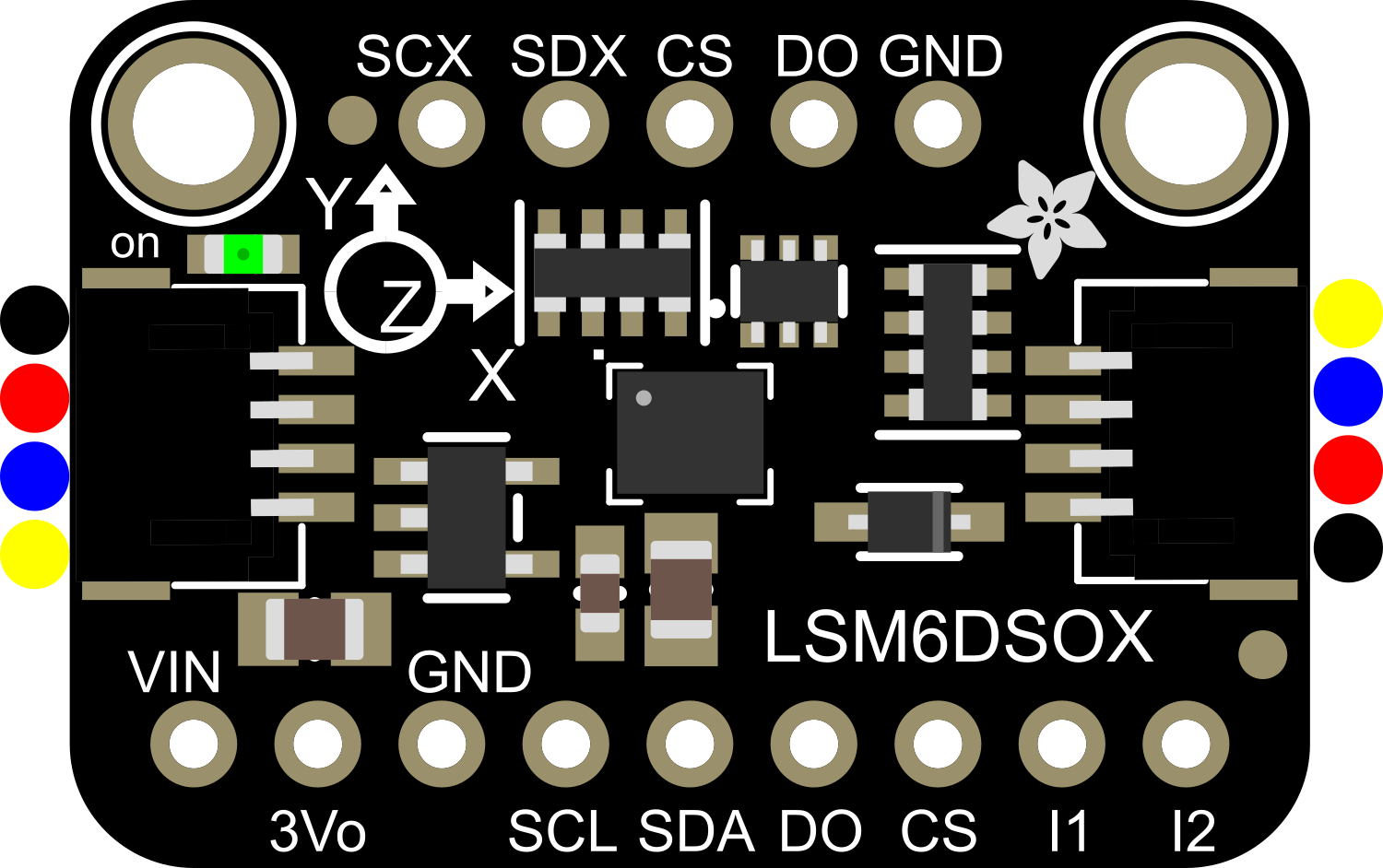
Pin Configuration
| Pin Number | Pin Name | Description |
|---|---|---|
| 1 | VDD | Power supply voltage (1.71 V to 3.6 V) |
| 2 | GND | Ground |
| 3 | SCL/SPC | I2C Serial Clock / SPI Serial Clock |
| 4 | SDA/SDI | I2C Serial Data / SPI Serial Data In |
| 5 | SA0/SDO | I2C Serial Address / SPI Serial Data Out |
| 6 | CS | SPI Chip Select (active low) |
| 7 | INT1 | Interrupt 1 (configurable) |
| 8 | INT2 | Interrupt 2 (configurable) |
Usage Instructions
Integration into a Circuit
To use the LSM6DSOX in a circuit:
- Connect VDD to a power supply within the specified range (1.71 V to 3.6 V).
- Connect GND to the ground of your system.
- For I2C communication, connect SCL to the I2C clock line and SDA to the I2C data line.
- For SPI communication, connect SPC to the SPI clock, SDI to the SPI data input, SDO to the SPI data output, and CS to the chip select line.
- Optionally, connect INT1 and INT2 to microcontroller pins if you plan to use the interrupt features.
Best Practices
- Use pull-up resistors on the I2C lines (SCL and SDA) if they are not already present on your microcontroller board.
- Keep the power supply stable and free of noise to ensure accurate sensor readings.
- Place the sensor away from sources of heat and electromagnetic interference.
- When using SPI, ensure that the CS line is held high when the device is not in use.
Example Code for Arduino UNO
#include <Wire.h>
#include <Adafruit_LSM6DSOX.h>

Adafruit_LSM6DSOX sox;

void setup() {
  Serial.begin(115200);
  // Wait for serial monitor to open
  while (!Serial) { delay(10); }

  Serial.println("LSM6DSOX test!");

  if (!sox.begin_I2C()) { // Can also use sox.begin_SPI(spi_cs_pin)
    Serial.println("Failed to find LSM6DSOX chip");
    while (1) {
      delay(10);
    }
  }
  Serial.println("LSM6DSOX Found!");
}

void loop() {
  // Read the sensor
  sensors_event_t accel;
  sensors_event_t gyro;
  sensors_event_t temp;
  sox.getEvent(&accel, &gyro, &temp);

  // Print out the values
  Serial.print("Accel X: "); Serial.print(accel.acceleration.x); Serial.println(" m/s^2");
  Serial.print("Accel Y: "); Serial.print(accel.acceleration.y); Serial.println(" m/s^2");
  Serial.print("Accel Z: "); Serial.print(accel.acceleration.z); Serial.println(" m/s^2");
  Serial.print("Gyro X: "); Serial.print(gyro.gyro.x); Serial.println(" dps");
  Serial.print("Gyro Y: "); Serial.print(gyro.gyro.y); Serial.println(" dps");
  Serial.print("Gyro Z: "); Serial.print(gyro.gyro.z); Serial.println(" dps");
  Serial.println();

  delay(100);
}
Troubleshooting and FAQs
Common Issues
- Sensor not detected: Ensure that the wiring is correct and that the correct voltage is applied. Check for soldering issues on the pins.
- Inaccurate readings: Verify that the sensor is calibrated correctly and that there are no strong magnetic fields or vibrations affecting the sensor.
- Interrupts not working: Make sure the INT1/INT2 pins are configured correctly in your code and that the microcontroller pins are set up to handle interrupts.
FAQs
Q: Can the LSM6DSOX be used with both I2C and SPI? A: Yes, the LSM6DSOX supports both I2C and SPI communication protocols.
Q: What is the purpose of the INT1 and INT2 pins? A: These pins can be configured to trigger interrupts for various events, such as motion detection or data ready signals.
Q: How do I calibrate the sensor? A: Calibration involves storing offset values for each axis. This can be done by reading the sensor output when the sensor is in a known stationary position and then subtracting these values from future readings.
Q: Is the LSM6DSOX suitable for outdoor use? A: While the LSM6DSOX can operate in a wide range of temperatures, it is not inherently weatherproof. Additional protection may be required for outdoor applications.
For further assistance, consult the Adafruit LSM6DSOX datasheet and the Adafruit support forums.