How to Use 3 position switch: Examples, Pinouts, and Specs
Introduction
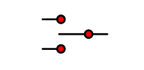
A 3-position switch is an electromechanical component that allows users to select one of three different circuit configurations. It is a versatile control element used in various applications, including industrial machinery, consumer electronics, automotive systems, and more. By toggling the switch, users can change the state of a device or circuit, selecting between three distinct modes or functions.
Explore Projects Built with 3 position switch

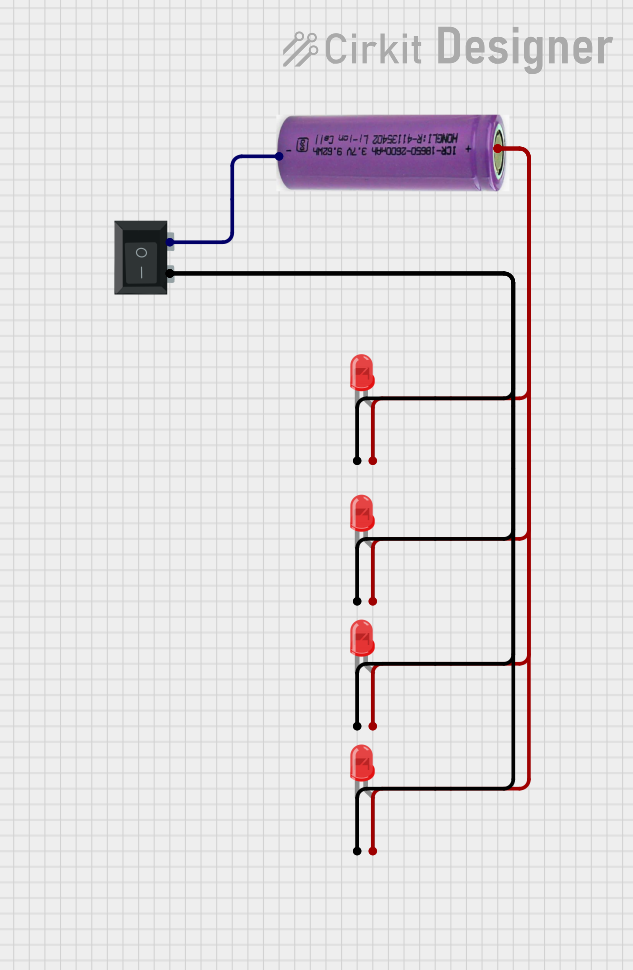
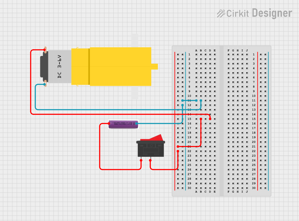
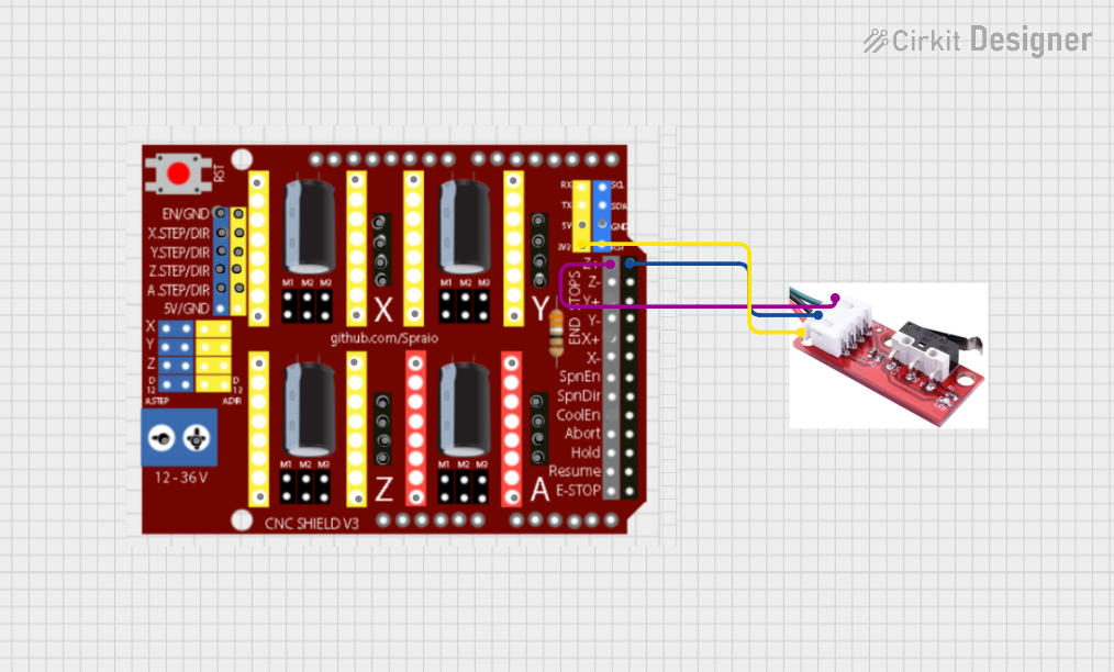
Explore Projects Built with 3 position switch
Technical Specifications
General Characteristics
- Switch Type: Rotary or Toggle
- Positions: 3 (e.g., ON-OFF-ON, ON-ON-ON)
- Contact Configuration: SPDT (Single Pole, Double Throw) or DPDT (Double Pole, Double Throw)
- Current Rating: Typically ranges from 1A to 20A
- Voltage Rating: Commonly up to 250V AC or 30V DC
- Terminal Type: Solder lugs, PCB pins, or screw terminals
- Actuator: Knob, lever, or slide
Pin Configuration and Descriptions
SPDT 3-Position Switch
| Pin Number | Description |
|---|---|
| 1 | Common terminal |
| 2 | Normally open (NO) |
| 3 | Normally closed (NC) |
DPDT 3-Position Switch
| Pin Number | Description |
|---|---|
| 1 | Common terminal 1 |
| 2 | Normally open (NO) 1 |
| 3 | Normally closed (NC) 1 |
| 4 | Common terminal 2 |
| 5 | Normally open (NO) 2 |
| 6 | Normally closed (NC) 2 |
Usage Instructions
Integration into a Circuit
- Identify the Type of Switch: Determine whether you have an SPDT or DPDT switch and understand the pin configuration.
- Wiring the Switch: Connect the common terminal(s) to the circuit's power source or signal line. The NO and NC terminals will be connected to the different circuit paths you wish to control.
- Mounting the Switch: Secure the switch to your device or enclosure, ensuring that it is accessible for operation.
Best Practices
- Load Rating: Do not exceed the current and voltage ratings of the switch to prevent damage.
- Debouncing: If using the switch for digital signals, consider implementing a debouncing circuit or software to avoid erratic behavior.
- Secure Connections: Ensure all terminals are properly connected and insulated to prevent short circuits.
Troubleshooting and FAQs
Common Issues
- Intermittent Operation: Check for loose connections or damaged terminals.
- Switch Does Not Maintain Position: The switch may be worn out and require replacement.
- Unexpected Circuit Behavior: Verify that the switch is wired correctly according to the desired circuit configuration.
FAQs
Q: Can I use a 3-position switch with an Arduino? A: Yes, you can use it to control different states in an Arduino project.
Q: How do I know if the switch is in the correct position? A: Some switches have a visual indicator or a distinct feel for each position. Otherwise, you can use a multimeter to test continuity.
Q: Is it possible to use the switch with AC and DC? A: Yes, but ensure the switch meets the required ratings for your specific application.
Example Code for Arduino UNO
// Define the switch input pin
const int switchPin = 2;

void setup() {
  // Set the switch pin as an input
  pinMode(switchPin, INPUT_PULLUP);
  Serial.begin(9600);
}

void loop() {
  // Read the state of the switch
  int switchState = digitalRead(switchPin);

  // Output the state to the Serial Monitor
  Serial.println(switchState);

  // Add your control logic here based on the switchState
  // ...

  delay(200); // Debounce delay
}
Note: The above code assumes a simple on-off-on type switch connected to a digital input with an internal pull-up resistor. Adjust the code and circuit as needed for your specific switch type and application.