How to Use BMP180 Breakout (GY-68): Examples, Pinouts, and Specs
Introduction
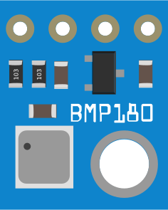
The BMP180 Breakout (GY-68) is a digital barometric pressure sensor designed to measure atmospheric pressure and temperature with high precision. It is based on Bosch's BMP180 sensor and is widely used in applications such as weather monitoring, altitude measurement, and environmental sensing. The module supports both I2C and SPI communication protocols, making it versatile and easy to integrate into microcontroller-based systems.
Explore Projects Built with BMP180 Breakout (GY-68)
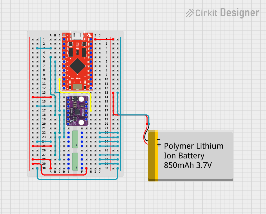
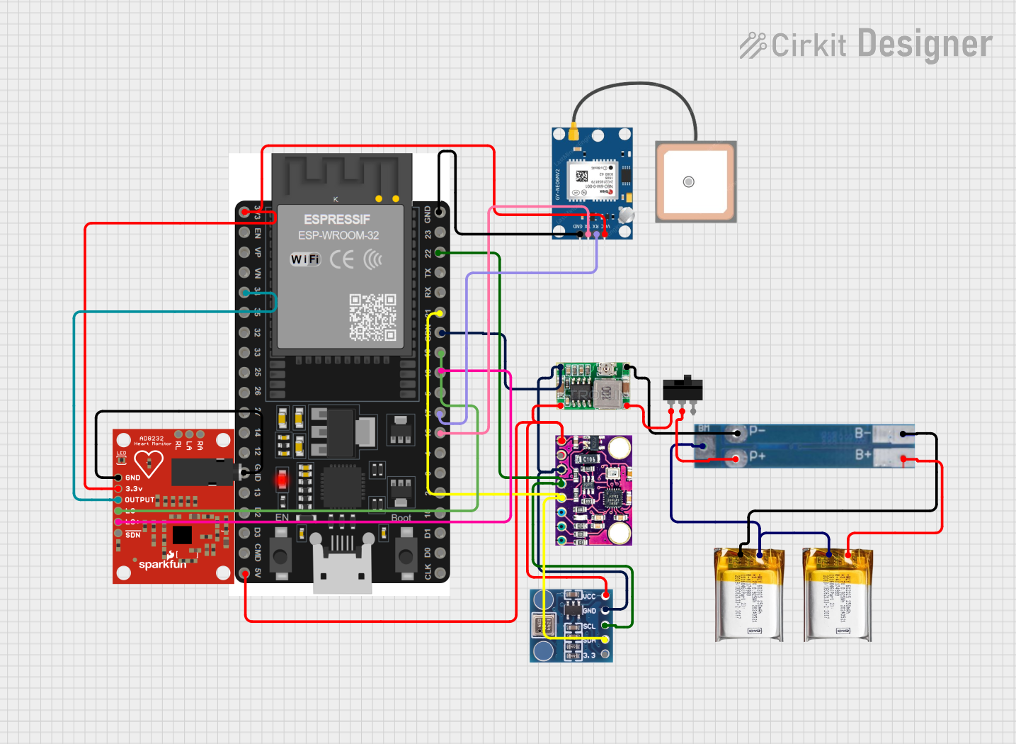
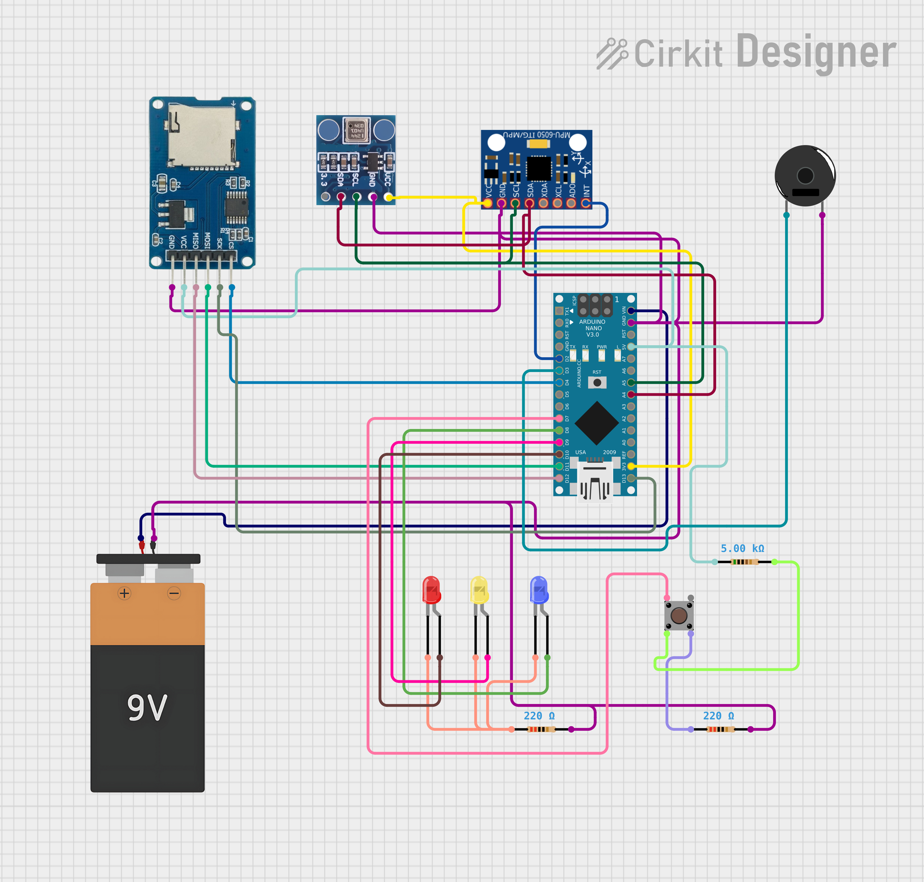
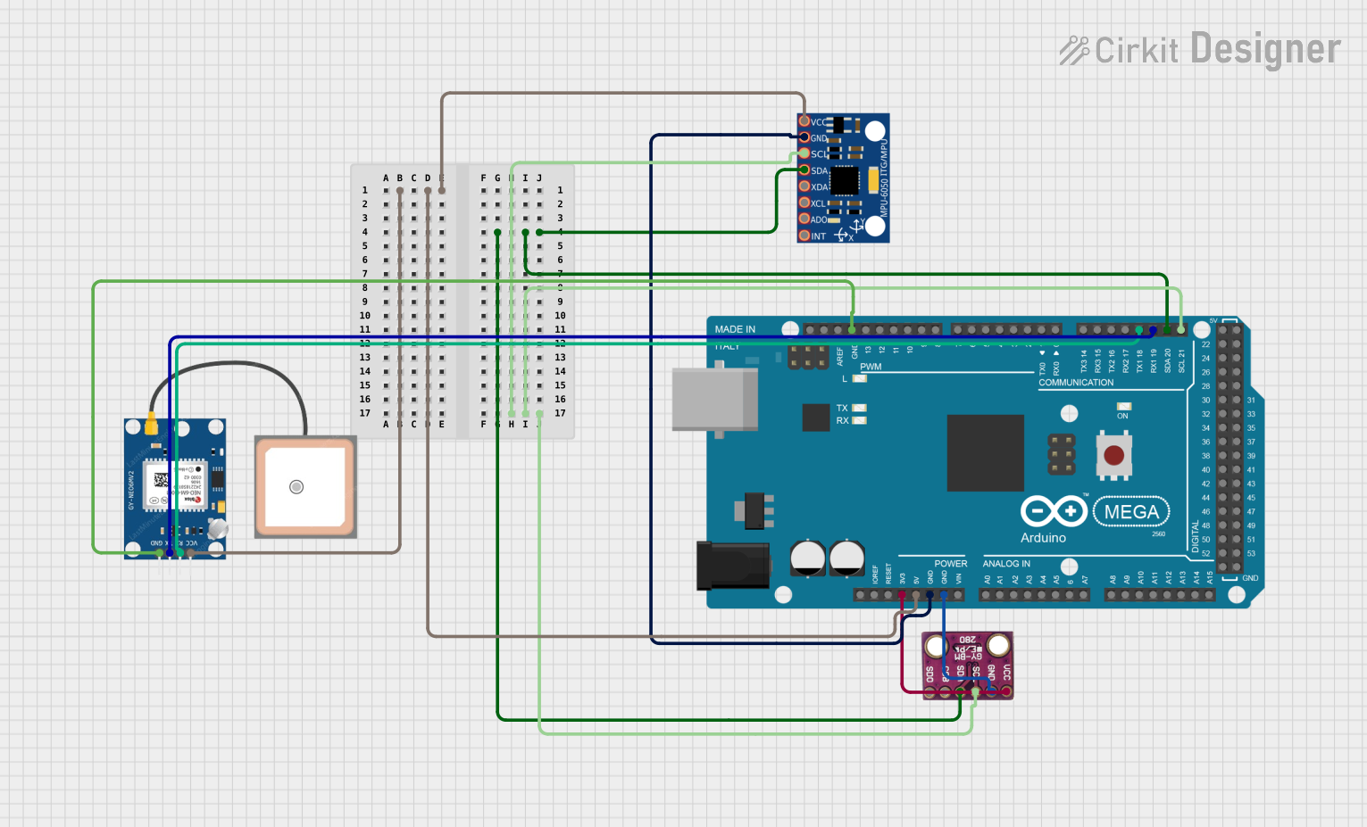
Explore Projects Built with BMP180 Breakout (GY-68)
Common Applications:
- Weather stations for monitoring atmospheric pressure and temperature
- Altitude measurement in drones, balloons, and other aerial devices
- Environmental sensing in IoT projects
- Indoor navigation and GPS enhancement
- Scientific experiments requiring precise pressure and temperature data
Technical Specifications
The BMP180 Breakout (GY-68) module has the following key technical details:
| Parameter | Value |
|---|---|
| Operating Voltage | 1.8V to 3.6V |
| Typical Operating Voltage | 3.3V |
| Communication Interface | I2C (default), SPI |
| Pressure Range | 300 hPa to 1100 hPa |
| Pressure Resolution | 0.01 hPa |
| Temperature Range | -40°C to +85°C |
| Temperature Resolution | 0.1°C |
| Power Consumption | 12 µA (typical in ultra-low power mode) |
| Dimensions | 21mm x 18mm x 2.5mm |
Pin Configuration and Descriptions
The BMP180 Breakout (GY-68) module has the following pinout:
| Pin | Name | Description |
|---|---|---|
| 1 | VIN | Power supply input (3.3V recommended, supports 1.8V to 3.6V) |
| 2 | GND | Ground connection |
| 3 | SCL | Serial Clock Line for I2C communication |
| 4 | SDA | Serial Data Line for I2C communication |
| 5 | XCLR | External reset input (optional, usually left unconnected) |
| 6 | EOC | End of Conversion signal (optional, used for SPI mode) |
| 7 | CSB | Chip Select for SPI mode (connect to GND for I2C mode) |
| 8 | VDDIO | I/O voltage reference (optional, typically tied to VIN) |
Usage Instructions
How to Use the BMP180 Breakout (GY-68) in a Circuit
- Power the Module: Connect the VIN pin to a 3.3V power source and the GND pin to ground.
- I2C Communication:
- Connect the SCL pin to the I2C clock line of your microcontroller.
- Connect the SDA pin to the I2C data line of your microcontroller.
- Ensure the CSB pin is connected to GND to enable I2C mode.
- Pull-Up Resistors: Use 4.7kΩ pull-up resistors on the SCL and SDA lines if your microcontroller does not have internal pull-ups.
- SPI Communication (optional):
- Connect the CSB pin to the SPI chip select line.
- Use the EOC pin for end-of-conversion signaling if required.
- Install Libraries: If using an Arduino, install the Adafruit BMP085/BMP180 library for easy integration.
Example Code for Arduino UNO
Below is an example of how to use the BMP180 Breakout (GY-68) with an Arduino UNO via I2C:
#include <Wire.h>
#include <Adafruit_Sensor.h>
#include <Adafruit_BMP085_U.h>

// Create an instance of the BMP180 sensor
Adafruit_BMP085_Unified bmp = Adafruit_BMP085_Unified(10085);

void setup() {
  Serial.begin(9600);
  Serial.println("BMP180 Sensor Test");

  // Initialize the sensor
  if (!bmp.begin()) {
    Serial.println("Could not find a valid BMP180 sensor, check wiring!");
    while (1); // Halt the program if the sensor is not detected
  }
}

void loop() {
  sensors_event_t event;
  bmp.getEvent(&event);

  if (event.pressure) {
    // Display pressure in hPa
    Serial.print("Pressure: ");
    Serial.print(event.pressure);
    Serial.println(" hPa");

    // Calculate and display altitude (assuming sea level pressure = 1013.25 hPa)
    float seaLevelPressure = 1013.25;
    Serial.print("Altitude: ");
    Serial.print(bmp.pressureToAltitude(seaLevelPressure, event.pressure));
    Serial.println(" m");

    // Display temperature
    float temperature;
    bmp.getTemperature(&temperature);
    Serial.print("Temperature: ");
    Serial.print(temperature);
    Serial.println(" °C");
  }

  delay(2000); // Wait 2 seconds before the next reading
}
Important Considerations and Best Practices
- Power Supply: Ensure the module is powered with a stable 3.3V source. Avoid exceeding the maximum voltage of 3.6V.
- I2C Address: The default I2C address of the BMP180 is
0x77. Ensure no other devices on the I2C bus share this address. - Altitude Calculation: For accurate altitude measurements, use the current sea-level pressure as a reference.
- Temperature Compensation: The BMP180 automatically compensates for temperature variations when measuring pressure.
Troubleshooting and FAQs
Common Issues and Solutions
Sensor Not Detected:
- Check the wiring, especially the connections to the SCL and SDA pins.
- Ensure the CSB pin is connected to GND for I2C mode.
- Verify that the I2C pull-up resistors are in place if required.
Incorrect Readings:
- Ensure the power supply voltage is stable and within the specified range.
- Verify that the sea-level pressure value used for altitude calculations is accurate.
No Data Output:
- Confirm that the correct I2C address (
0x77) is being used in the code. - Check for loose or incorrect connections.
- Confirm that the correct I2C address (
FAQs
Q: Can the BMP180 measure negative altitudes?
A: Yes, the BMP180 can measure altitudes below sea level, provided the correct sea-level pressure is used as a reference.
Q: What is the maximum altitude the BMP180 can measure?
A: The BMP180 can measure altitudes up to approximately 9,000 meters, depending on the atmospheric pressure.
Q: Can I use the BMP180 with a 5V microcontroller?
A: Yes, but you must use a logic level shifter to step down the 5V signals to 3.3V for the BMP180.
Q: How accurate is the BMP180?
A: The BMP180 has a typical pressure accuracy of ±1 hPa and a temperature accuracy of ±2°C.
By following this documentation, you can effectively integrate the BMP180 Breakout (GY-68) into your projects for reliable pressure and temperature measurements.