How to Use Battery Level Indicator: Examples, Pinouts, and Specs
Introduction
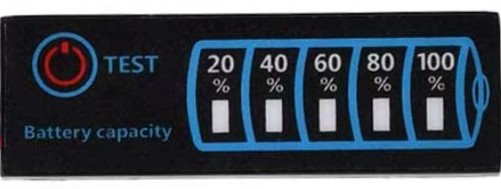
A Battery Level Indicator is an electronic component designed to display the current charge level of a battery. It typically uses LEDs, a digital display, or other visual indicators to show whether the battery is full, half-charged, or low. This component is essential in battery-powered devices to monitor power levels and prevent unexpected shutdowns.
Explore Projects Built with Battery Level Indicator
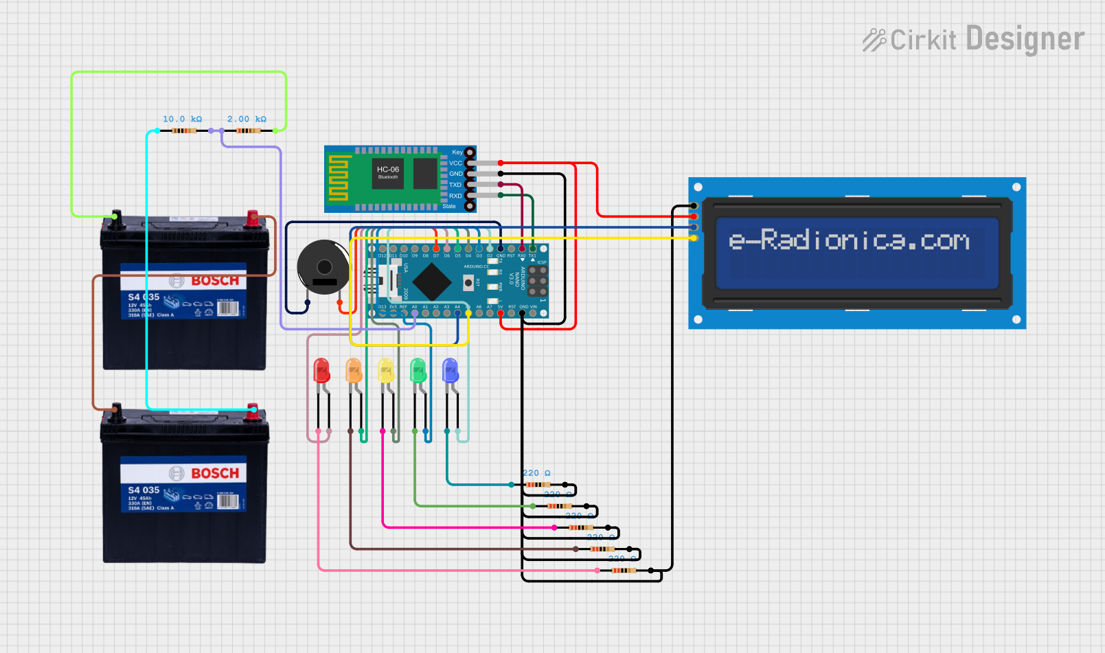

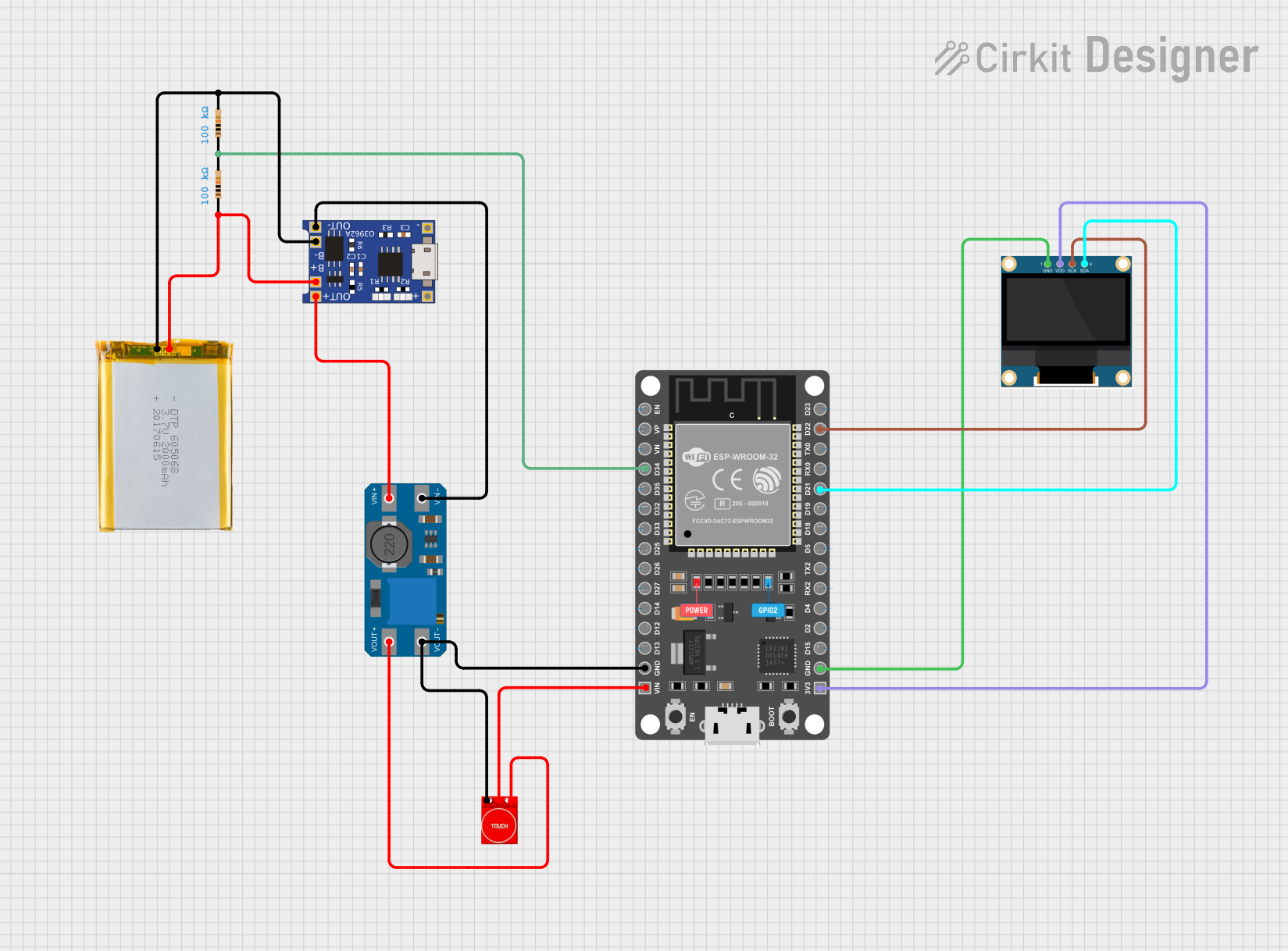
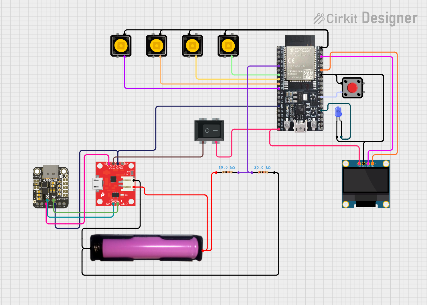
Explore Projects Built with Battery Level Indicator
Common Applications and Use Cases
- Portable electronic devices (e.g., power banks, flashlights)
- Electric vehicles and bicycles
- Solar power systems
- Uninterruptible Power Supplies (UPS)
- DIY electronics projects
Technical Specifications
Below are the general technical specifications for a typical Battery Level Indicator. Specifications may vary depending on the specific model or design.
Key Technical Details
- Operating Voltage: 3V to 24V (depending on the design)
- Current Consumption: Typically 10mA to 50mA
- Display Type: LED bar graph, 7-segment display, or LCD
- Battery Compatibility: Lithium-ion, lead-acid, NiMH, or alkaline batteries
- Accuracy: ±5% (varies by model)
- Operating Temperature: -10°C to 60°C
Pin Configuration and Descriptions
The pin configuration for a Battery Level Indicator module with an LED bar graph is as follows:
| Pin Name | Description |
|---|---|
| VCC | Positive power supply input (connect to battery positive terminal). |
| GND | Ground connection (connect to battery negative terminal). |
| IN+ | Positive voltage sense input (connect to the battery terminal to be monitored). |
| IN- | Negative voltage sense input (optional, used in some designs). |
| LED1-LEDN | Outputs for individual LEDs (indicate battery level, e.g., LED1 = low, LEDN = full). |
For digital display-based indicators, the pinout may include additional pins for data communication (e.g., I2C or SPI).
Usage Instructions
How to Use the Component in a Circuit
- Power Connection: Connect the
VCCpin to the positive terminal of the battery and theGNDpin to the negative terminal. - Voltage Sensing: Attach the
IN+pin to the battery's positive terminal. If the design includes anIN-pin, connect it to the battery's negative terminal. - LED Outputs: If using an LED-based indicator, connect the
LED1toLEDNpins to the corresponding LEDs. Ensure the LEDs are connected with appropriate current-limiting resistors. - Digital Display: For digital indicators, connect the display pins as per the manufacturer's datasheet. If communication protocols like I2C or SPI are used, connect the data and clock lines to the microcontroller.
Important Considerations and Best Practices
- Voltage Range: Ensure the indicator's operating voltage matches the battery's voltage range.
- Current Limiting: Use resistors to limit current through LEDs to prevent damage.
- Calibration: Some indicators may require calibration to accurately reflect battery levels.
- Heat Management: Avoid overheating by ensuring proper ventilation or heat dissipation.
- Microcontroller Integration: If connecting to a microcontroller (e.g., Arduino UNO), ensure proper voltage level matching.
Example: Using a Battery Level Indicator with Arduino UNO
Below is an example of how to use a Battery Level Indicator with an Arduino UNO to monitor a 12V battery and display the level using LEDs.
Circuit Diagram
- Connect the
VCCpin of the indicator to the 12V battery positive terminal. - Connect the
GNDpin to the battery negative terminal. - Connect the
IN+pin to the battery positive terminal. - Connect the
LED1toLEDNpins to digital pins on the Arduino (e.g., D2 to D6).
Arduino Code
// Define LED pins for battery level indication
const int ledPins[] = {2, 3, 4, 5, 6}; // Connect LEDs to these pins
const int numLeds = 5; // Number of LEDs used

void setup() {
  // Initialize LED pins as outputs
  for (int i = 0; i < numLeds; i++) {
    pinMode(ledPins[i], OUTPUT);
  }
}

void loop() {
  // Simulate battery voltage levels (replace with actual sensor readings)
  int batteryLevel = analogRead(A0); // Read battery voltage on analog pin A0
  int mappedLevel = map(batteryLevel, 0, 1023, 0, numLeds);

  // Turn on LEDs based on battery level
  for (int i = 0; i < numLeds; i++) {
    if (i < mappedLevel) {
      digitalWrite(ledPins[i], HIGH); // Turn on LED
    } else {
      digitalWrite(ledPins[i], LOW); // Turn off LED
    }
  }

  delay(500); // Update every 500ms
}
Troubleshooting and FAQs
Common Issues and Solutions
LEDs Not Lighting Up:
- Check the power supply connections to ensure proper voltage and polarity.
- Verify that current-limiting resistors are correctly installed.
- Ensure the battery voltage is within the indicator's operating range.
Inaccurate Battery Level Display:
- Calibrate the indicator if required (refer to the manufacturer's instructions).
- Check for loose or faulty connections in the circuit.
Overheating:
- Ensure the indicator is not drawing excessive current.
- Use proper heat dissipation methods if necessary.
No Response from Digital Display:
- Verify the communication protocol (e.g., I2C or SPI) and ensure proper wiring.
- Check the microcontroller code for errors in data transmission.
FAQs
Q: Can I use this indicator with a 24V battery?
A: Yes, if the indicator's operating voltage supports 24V. Check the specifications before use.
Q: Do I need a microcontroller to use this component?
A: No, a microcontroller is not required for basic LED-based indicators. However, it is needed for advanced features like digital displays or data logging.
Q: How do I know if the indicator is compatible with my battery type?
A: Check the indicator's datasheet for supported battery chemistries (e.g., lithium-ion, lead-acid).
Q: Can I use this with rechargeable and non-rechargeable batteries?
A: Yes, as long as the battery voltage is within the indicator's operating range.