How to Use Flame Sensor: Examples, Pinouts, and Specs
Introduction
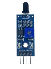
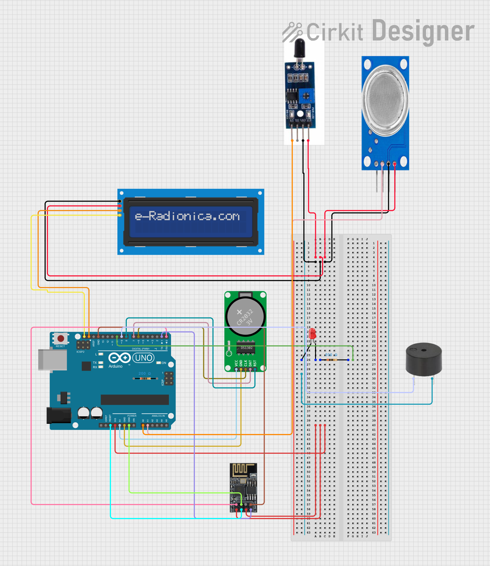
A flame sensor is an electronic device that detects the presence of a flame or fire, primarily by sensing the infrared (IR) light emitted by the flame. These sensors are widely used in various safety and fire detection systems, including gas stoves, furnaces, and industrial flame monitoring. They can also be integrated into hobbyist projects for fire alarms or robotics, often interfaced with microcontrollers like the Arduino UNO.
Explore Projects Built with Flame Sensor
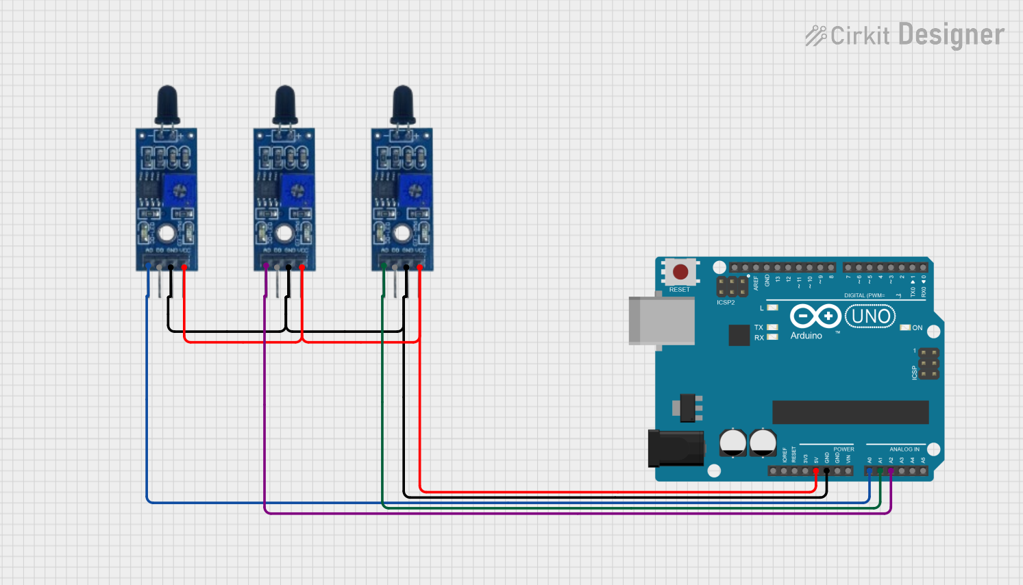
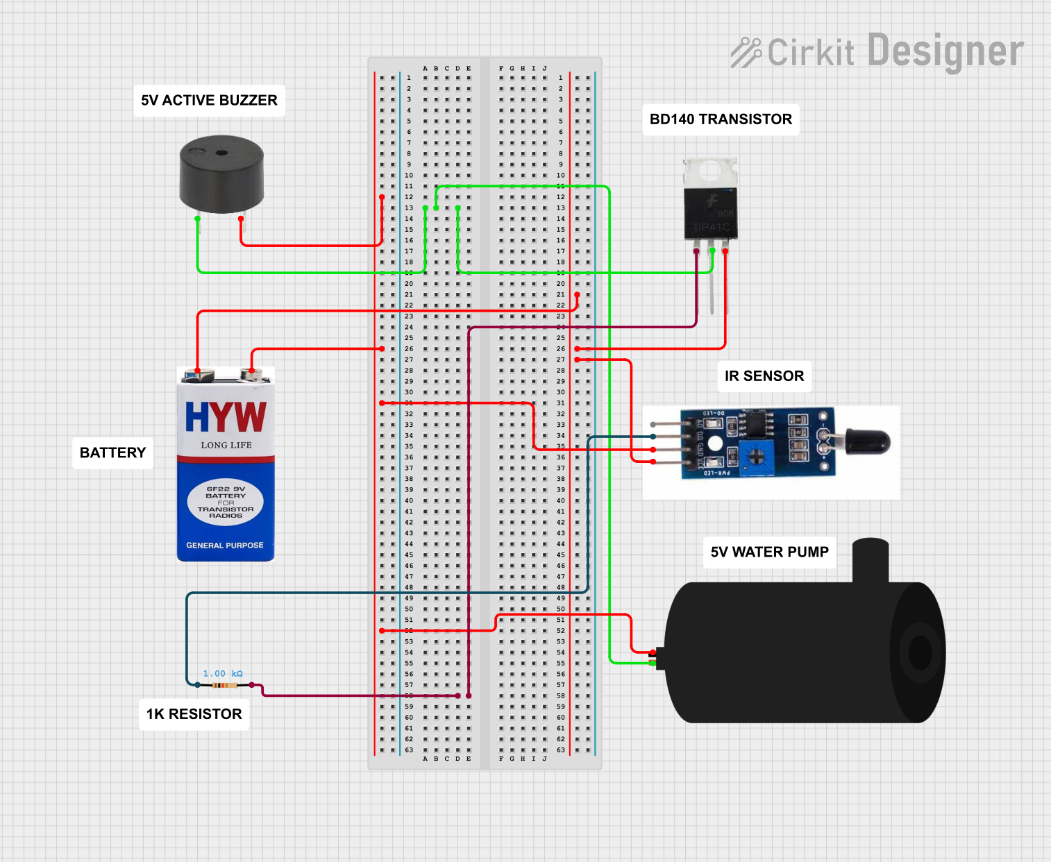
Explore Projects Built with Flame Sensor
Technical Specifications
Key Technical Details
- Operating Voltage: Typically 3.3V to 5V
- Current Consumption: 15mA (typical)
- Spectral Response: 760nm to 1100nm (IR range)
- Detection Angle: 60 degrees
- Output Type: Digital (High/Low signal)
Pin Configuration and Descriptions
| Pin Number | Name | Description |
|---|---|---|
| 1 | VCC | Connect to 3.3V-5V power supply |
| 2 | GND | Connect to ground |
| 3 | DO | Digital output; connects to a digital pin on a microcontroller |
| 4 | AO | Analog output; connects to an analog pin on a microcontroller (optional) |
Usage Instructions
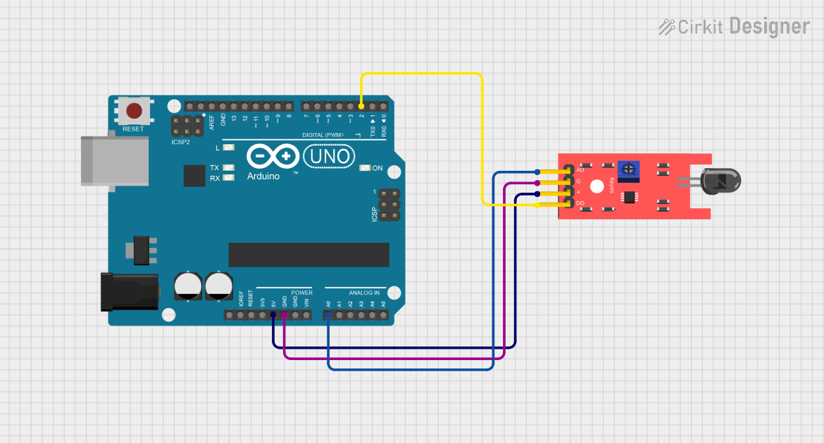
Interfacing with a Circuit
- Power Connections: Connect the VCC pin to a 3.3V-5V power supply and the GND pin to the ground.
- Output Connection: Connect the DO pin to a digital input pin on your microcontroller. If analog measurement is needed, connect the AO pin to an analog input pin.
- Adjust Sensitivity: Some flame sensors come with a potentiometer to adjust the sensitivity. Turn the potentiometer until the sensor responds to a flame at the desired distance.
Important Considerations and Best Practices
- Distance to Flame: The sensor should be placed at a safe distance from the flame to avoid damage.
- Ambient Light: Be aware of ambient light that may interfere with the sensor's ability to detect a flame.
- Testing: Always test the sensor in controlled conditions before deploying it in a critical safety application.
- Heat Protection: If the sensor is used near high temperatures, ensure it is adequately shielded or cooled.
Example Code for Arduino UNO
// Define the digital input pin where the flame sensor is connected
const int flameSensorPin = 2;

void setup() {
  pinMode(flameSensorPin, INPUT);
  Serial.begin(9600);
}

void loop() {
  int flameDetected = digitalRead(flameSensorPin);

  // If the sensor's digital output goes LOW, a flame is detected
  if (flameDetected == LOW) {
    Serial.println("Flame detected!");
  } else {
    Serial.println("No flame detected.");
  }

  // Wait for a short period before reading again
  delay(200);
}
Troubleshooting and FAQs
Common Issues
- False Alarms: Adjust the sensitivity potentiometer to reduce false positives.
- No Response: Ensure the sensor is correctly powered and the pins are properly connected.
- Intermittent Signals: Check for loose connections and ensure the sensor is not exposed to intermittent light sources that could trigger false readings.
Solutions and Tips
- Shielding from Ambient Light: Use a tube or shield to block out ambient light.
- Regular Testing: Periodically test the sensor to ensure it is functioning correctly.
- Avoid Obstructions: Ensure the sensor's field of view is not obstructed by objects that could block the IR light from a flame.
FAQs
Q: Can the flame sensor detect smoke? A: No, flame sensors are designed to detect IR light from flames, not smoke particles.
Q: What is the maximum distance the sensor can detect a flame? A: This depends on the sensor's sensitivity and the size of the flame, but typically it is within a few feet.
Q: Can I use the flame sensor with a 3.3V system? A: Yes, most flame sensors can operate at 3.3V, but always check the specific sensor's datasheet.
Q: How do I know if the sensor is working? A: You can test the sensor by exposing it to a safe flame source, like a lighter, and observing the output signal.
Remember to always handle flame sensors with care and to use them responsibly in any application. Safety should be your top priority when working with devices that detect fire or flames.