Cirkit Designer Logo
Cirkit Designer
Your all-in-one circuit design IDE
Home / 
Component Documentation

How to Use Modulino Buzzer: Examples, Pinouts, and Specs

Image of Modulino Buzzer
Cirkit Designer LogoDesign with Modulino Buzzer in Cirkit Designer

Introduction

The Modulino Buzzer is a small electronic device designed to produce sound when an electrical signal is applied. It is commonly used in alarms, notifications, and sound effects for various electronic projects. This versatile component is ideal for hobbyists, students, and professionals working on Arduino-based projects, embedded systems, or other electronic circuits requiring audio feedback.

Explore Projects Built with Modulino Buzzer

Use Cirkit Designer to design, explore, and prototype these projects online. Some projects support real-time simulation. Click "Open Project" to start designing instantly!
Wi-Fi Controlled Buzzer with Wemos D1 Mini
Image of Buzzer Twinkle: A project utilizing Modulino Buzzer in a practical application
This circuit consists of a Wemos D1 Mini microcontroller connected to an active buzzer module. The Wemos D1 Mini provides power to the buzzer and controls it through its D1 pin, allowing for programmable sound output.
Cirkit Designer LogoOpen Project in Cirkit Designer
IoT-Enabled Environmental Monitoring System with NUCLEO-F303RE and ESP8266
Image of GAS LEAKAGE DETECTION: A project utilizing Modulino Buzzer in a practical application
This circuit features a NUCLEO-F303RE microcontroller board interfaced with various modules for sensing, actuation, and communication. It includes an MQ-2 gas sensor for detecting combustible gases, a buzzer for audible alerts, and a relay for controlling high-power devices. Additionally, the circuit uses an ESP8266 WiFi module for wireless connectivity and an I2C LCD display for user interface and data display.
Cirkit Designer LogoOpen Project in Cirkit Designer
Voice-Controlled Buzzer System with VC-02 Module
Image of vc: A project utilizing Modulino Buzzer in a practical application
This circuit features a VC-02 voice recognition module connected to a buzzer and powered by a 5V battery. The VC-02 module is programmed to listen for specific voice commands and, upon recognizing the command 'can you make a sound', it activates the buzzer for one second. The circuit is designed for voice-activated sound generation, with the VC-02 module handling voice recognition and serial communication, and the buzzer providing audible feedback.
Cirkit Designer LogoOpen Project in Cirkit Designer
Arduino UNO OLED Display and Buzzer Melody Project
Image of ardunio_uno_buzzer_happy_oled: A project utilizing Modulino Buzzer in a practical application
This circuit features an Arduino UNO microcontroller that drives a 0.96" OLED display and a buzzer module. The OLED display shows a bitmap image, while the buzzer plays a melody upon initialization.
Cirkit Designer LogoOpen Project in Cirkit Designer

Explore Projects Built with Modulino Buzzer

Use Cirkit Designer to design, explore, and prototype these projects online. Some projects support real-time simulation. Click "Open Project" to start designing instantly!
Image of Buzzer Twinkle: A project utilizing Modulino Buzzer in a practical application
Wi-Fi Controlled Buzzer with Wemos D1 Mini
This circuit consists of a Wemos D1 Mini microcontroller connected to an active buzzer module. The Wemos D1 Mini provides power to the buzzer and controls it through its D1 pin, allowing for programmable sound output.
Cirkit Designer LogoOpen Project in Cirkit Designer
Image of GAS LEAKAGE DETECTION: A project utilizing Modulino Buzzer in a practical application
IoT-Enabled Environmental Monitoring System with NUCLEO-F303RE and ESP8266
This circuit features a NUCLEO-F303RE microcontroller board interfaced with various modules for sensing, actuation, and communication. It includes an MQ-2 gas sensor for detecting combustible gases, a buzzer for audible alerts, and a relay for controlling high-power devices. Additionally, the circuit uses an ESP8266 WiFi module for wireless connectivity and an I2C LCD display for user interface and data display.
Cirkit Designer LogoOpen Project in Cirkit Designer
Image of vc: A project utilizing Modulino Buzzer in a practical application
Voice-Controlled Buzzer System with VC-02 Module
This circuit features a VC-02 voice recognition module connected to a buzzer and powered by a 5V battery. The VC-02 module is programmed to listen for specific voice commands and, upon recognizing the command 'can you make a sound', it activates the buzzer for one second. The circuit is designed for voice-activated sound generation, with the VC-02 module handling voice recognition and serial communication, and the buzzer providing audible feedback.
Cirkit Designer LogoOpen Project in Cirkit Designer
Image of ardunio_uno_buzzer_happy_oled: A project utilizing Modulino Buzzer in a practical application
Arduino UNO OLED Display and Buzzer Melody Project
This circuit features an Arduino UNO microcontroller that drives a 0.96" OLED display and a buzzer module. The OLED display shows a bitmap image, while the buzzer plays a melody upon initialization.
Cirkit Designer LogoOpen Project in Cirkit Designer

Technical Specifications

  • Type: Active Buzzer
  • Operating Voltage: 3.3V to 5V DC
  • Current Consumption: ≤ 30mA
  • Sound Frequency: ~2 kHz
  • Sound Pressure Level: ≥ 85 dB at 10 cm
  • Dimensions: 12mm diameter, 8mm height
  • Operating Temperature: -20°C to 70°C

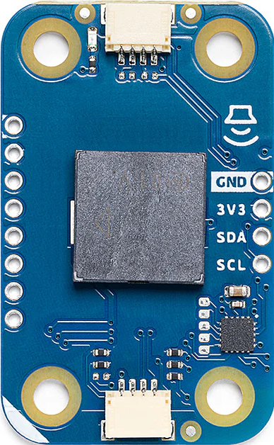
Pin Configuration and Descriptions

The Modulino Buzzer typically has two pins for connection:

Pin Name Description Notes
VCC Positive power supply input Connect to 3.3V or 5V DC
GND Ground connection Connect to circuit ground

Usage Instructions

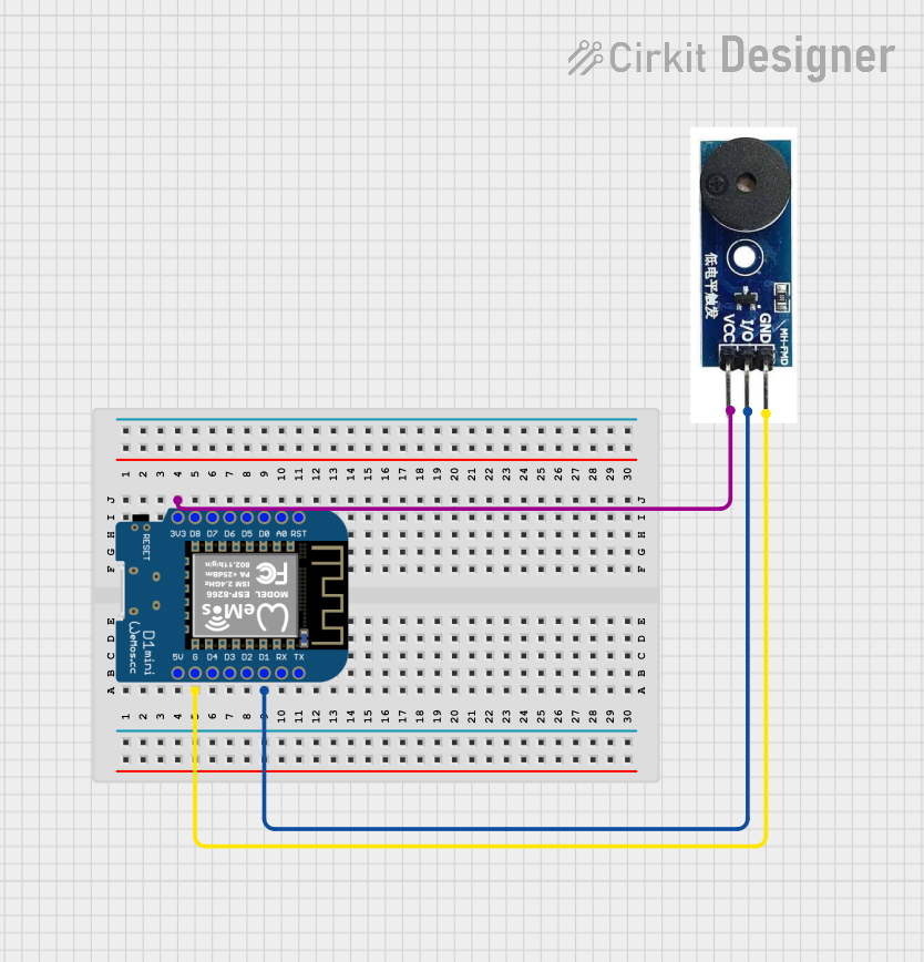
How to Use the Modulino Buzzer in a Circuit

  1. Power Connection: Connect the VCC pin of the buzzer to a 3.3V or 5V power source, depending on your circuit's voltage level. Connect the GND pin to the ground of your circuit.
  2. Control Signal: For an active buzzer, simply apply a HIGH signal to the VCC pin to produce sound. No additional circuitry is required to generate the tone.
  3. Placement: Ensure the buzzer is securely mounted on your PCB or breadboard. Avoid placing it near sensitive components to minimize interference.

Important Considerations and Best Practices

  • Voltage Compatibility: Ensure the operating voltage of the buzzer matches your circuit's power supply to avoid damage.
  • Polarity: The Modulino Buzzer is polarized. Connecting it incorrectly may prevent it from functioning or cause damage.
  • Distance: For optimal sound output, place the buzzer in an open area, away from obstructions.
  • Current Limiting: If your circuit's power source is limited, consider using a current-limiting resistor to protect the buzzer and other components.

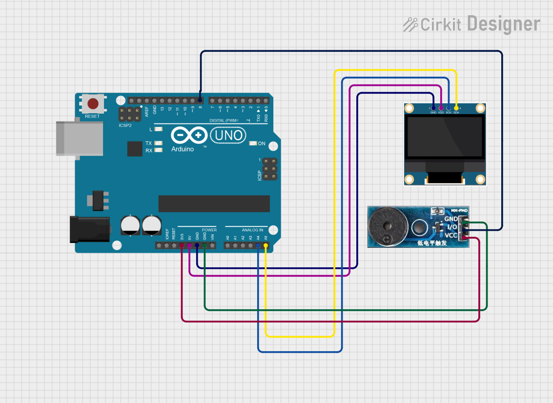
Example: Using the Modulino Buzzer with an Arduino UNO

Below is an example of how to connect and control the Modulino Buzzer using an Arduino UNO:

// Modulino Buzzer Example with Arduino UNO
// This code produces a beep sound every second using the Modulino Buzzer.

const int buzzerPin = 8; // Define the pin connected to the buzzer

void setup() {
  pinMode(buzzerPin, OUTPUT); // Set the buzzer pin as an output
}

void loop() {
  digitalWrite(buzzerPin, HIGH); // Turn the buzzer ON
  delay(500);                   // Wait for 500 milliseconds
  digitalWrite(buzzerPin, LOW);  // Turn the buzzer OFF
  delay(500);                   // Wait for 500 milliseconds
}

Note: Ensure the buzzerPin is connected to the VCC pin of the Modulino Buzzer, and the GND pin is connected to the Arduino's ground.

Troubleshooting and FAQs

Common Issues Users Might Face

  1. No Sound Output:

    • Cause: Incorrect wiring or reversed polarity.
    • Solution: Double-check the connections and ensure the VCC pin is connected to the positive voltage and the GND pin to ground.
  2. Low Sound Volume:

    • Cause: Insufficient power supply or obstructions near the buzzer.
    • Solution: Verify the power supply voltage and ensure the buzzer is placed in an open area.
  3. Intermittent Sound:

    • Cause: Loose connections or unstable power supply.
    • Solution: Secure all connections and use a stable power source.
  4. Buzzer Always ON:

    • Cause: Continuous HIGH signal applied to the VCC pin.
    • Solution: Check your control signal logic and ensure the buzzer is toggled appropriately.

FAQs

  • Q: Can I use the Modulino Buzzer with a 9V battery?
    A: No, the Modulino Buzzer is designed for 3.3V to 5V operation. Using a 9V battery may damage the component.

  • Q: Is the Modulino Buzzer waterproof?
    A: No, the Modulino Buzzer is not waterproof. Avoid exposing it to moisture or water.

  • Q: Can I control the sound frequency of the Modulino Buzzer?
    A: No, the Modulino Buzzer is an active buzzer with a fixed frequency (~2 kHz). For variable frequencies, consider using a passive buzzer.

  • Q: How far can the sound of the Modulino Buzzer be heard?
    A: The sound pressure level is ≥ 85 dB at 10 cm. The audible range depends on environmental factors and background noise.

By following this documentation, you can effectively integrate the Modulino Buzzer into your electronic projects and troubleshoot any issues that arise.