How to Use 2x6 Position Terminal Block Distribution Module: Examples, Pinouts, and Specs
Introduction
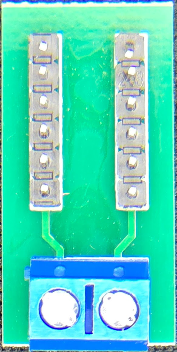
The 2x6 Position Terminal Block Distribution Module is a versatile and reliable component designed to provide a secure connection point for multiple wires. It features two rows with six positions each, allowing for easy distribution of electrical signals or power across multiple circuits. This module is commonly used in industrial control systems, home automation, and prototyping projects where organized wiring and robust connections are essential.
Explore Projects Built with 2x6 Position Terminal Block Distribution Module


Explore Projects Built with 2x6 Position Terminal Block Distribution Module
Common Applications
- Industrial control panels
- Power distribution in automation systems
- Prototyping and breadboarding
- Home automation and IoT projects
- Signal distribution in audio or communication systems
Technical Specifications
The following table outlines the key technical details of the 2x6 Position Terminal Block Distribution Module:
| Parameter | Specification |
|---|---|
| Number of Positions | 2 rows, 6 positions (12 terminals) |
| Rated Voltage | Up to 300V AC/DC |
| Rated Current | Up to 15A |
| Wire Gauge Compatibility | 22-12 AWG |
| Material | Flame-retardant plastic (housing) |
| Terminal Type | Screw-type |
| Mounting Style | PCB mount or DIN rail (optional) |
| Operating Temperature | -40°C to 105°C |
Pin Configuration and Descriptions
The terminal block does not have traditional "pins" like an IC but instead features screw terminals for wire connections. Below is a description of the terminal layout:
| Position | Description |
|---|---|
| 1-6 (Row 1) | Positive or signal connections (e.g., V+, Signal) |
| 7-12 (Row 2) | Negative or ground connections (e.g., GND) |
Each terminal is clearly labeled on the module for easy identification.
Usage Instructions
How to Use the Component in a Circuit
- Prepare the Wires: Strip the insulation from the ends of the wires you intend to connect. Ensure the exposed wire length matches the terminal block's specifications (typically 5-7mm).
- Insert the Wires: Loosen the screws on the terminal block using a screwdriver. Insert the stripped wire ends into the appropriate terminals.
- Secure the Connection: Tighten the screws to secure the wires in place. Ensure the connection is firm but avoid overtightening, which could damage the wires or the terminal block.
- Connect to the Circuit: Mount the terminal block on a PCB or DIN rail as required. Connect the other ends of the wires to the corresponding components in your circuit.
Important Considerations and Best Practices
- Wire Gauge: Use wires within the supported range (22-12 AWG) to ensure a secure connection.
- Current and Voltage Ratings: Do not exceed the rated current (15A) or voltage (300V) to avoid overheating or damage.
- Tightening Screws: Use an appropriately sized screwdriver to avoid stripping the screws.
- Mounting: If using the PCB mount version, ensure the solder joints are clean and secure. For DIN rail mounting, verify that the module is firmly attached to the rail.
Example: Connecting to an Arduino UNO
The terminal block can be used to distribute power or signals to multiple devices connected to an Arduino UNO. Below is an example of how to use the terminal block to distribute a 5V power supply:
Circuit Setup
- Connect the Arduino's 5V pin to one of the terminals in Row 1 (e.g., Position 1).
- Connect the Arduino's GND pin to one of the terminals in Row 2 (e.g., Position 7).
- Use the remaining terminals in Row 1 and Row 2 to distribute 5V and GND to other devices (e.g., sensors, LEDs).
Sample Code
// Example code for powering multiple LEDs using the terminal block
// Connect the positive terminals of the LEDs to Row 1 (5V)
// Connect the negative terminals of the LEDs to Row 2 (GND)

const int ledPins[] = {2, 3, 4, 5, 6}; // Arduino pins connected to LEDs

void setup() {
  // Set all LED pins as OUTPUT
  for (int i = 0; i < 5; i++) {
    pinMode(ledPins[i], OUTPUT);
  }
}

void loop() {
  // Blink all LEDs in sequence
  for (int i = 0; i < 5; i++) {
    digitalWrite(ledPins[i], HIGH); // Turn LED on
    delay(500);                    // Wait for 500ms
    digitalWrite(ledPins[i], LOW); // Turn LED off
    delay(500);                    // Wait for 500ms
  }
}
Troubleshooting and FAQs
Common Issues
Loose Connections: If a wire is not securely fastened, it may cause intermittent connections or signal loss.
- Solution: Ensure the screws are tightened properly and the wire is fully inserted into the terminal.
Overheating: The terminal block may overheat if the current exceeds the rated 15A.
- Solution: Verify that the connected devices do not draw more current than the terminal block's rating.
Wire Slippage: Thin wires may slip out of the terminal if not properly secured.
- Solution: Use wires within the supported gauge range (22-12 AWG) and ensure the screws are tightened evenly.
Short Circuits: Adjacent terminals may short if wires are improperly stripped or frayed.
- Solution: Ensure wires are neatly stripped and no exposed strands are touching adjacent terminals.
FAQs
Q: Can this terminal block be used for AC power distribution?
A: Yes, the terminal block supports both AC and DC power distribution up to 300V.
Q: Is the module compatible with stranded wires?
A: Yes, it is compatible with both solid and stranded wires. For stranded wires, it is recommended to use ferrules for a more secure connection.
Q: Can I use this terminal block outdoors?
A: The terminal block is not weatherproof. For outdoor use, ensure it is housed in a weather-resistant enclosure.
Q: How do I mount the terminal block on a PCB?
A: The PCB mount version includes solderable pins. Align the pins with the PCB holes, solder them securely, and verify the connections.
By following this documentation, you can effectively use the 2x6 Position Terminal Block Distribution Module in your projects for safe and organized wiring.