How to Use SN74LVC1T45: Examples, Pinouts, and Specs
Introduction
The SN74LVC1T45 is a single-bit, dual-supply level shifter manufactured by Texas Instruments. It is designed to enable bidirectional voltage translation between two different voltage levels, making it an essential component for interfacing devices operating at different logic levels. This component is highly versatile and supports a wide range of voltage levels, making it suitable for modern low-power and mixed-voltage systems.
Explore Projects Built with SN74LVC1T45


Explore Projects Built with SN74LVC1T45
Common Applications and Use Cases
- Interfacing between 1.8V, 3.3V, and 5V logic devices.
- Communication between microcontrollers and peripherals with differing voltage levels.
- Voltage level translation in I²C, SPI, or UART communication protocols.
- Mixed-voltage systems in consumer electronics, industrial automation, and IoT devices.
Technical Specifications
Key Technical Details
- Operating Voltage Range:
- VCCA: 1.65V to 5.5V
- VCCB: 1.65V to 5.5V
- Data Rate:
- Up to 380 Mbps (push-pull configuration)
- Up to 24 Mbps (open-drain configuration)
- Input/Output Type: CMOS
- Operating Temperature Range: -40°C to 125°C
- Drive Strength: ±24 mA at 3.3V
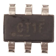
- Package Options: SOT-23, SC-70, and others.
Pin Configuration and Descriptions
The SN74LVC1T45 is available in a 6-pin SOT-23 or SC-70 package. Below is the pinout and description:
| Pin | Name | Type | Description |
|---|---|---|---|
| 1 | DIR | Input | Direction control pin. High = A to B, Low = B to A. |
| 2 | A | Input/Output | Data input/output pin for side A. |
| 3 | GND | Ground | Ground connection. |
| 4 | B | Input/Output | Data input/output pin for side B. |
| 5 | VCCB | Power Supply | Supply voltage for side B (1.65V to 5.5V). |
| 6 | VCCA | Power Supply | Supply voltage for side A (1.65V to 5.5V). |
Usage Instructions
How to Use the SN74LVC1T45 in a Circuit
Power Supply Connections:
- Connect VCCA to the supply voltage of the device on side A.
- Connect VCCB to the supply voltage of the device on side B.
- Ensure that both supply voltages are within the specified range (1.65V to 5.5V).
Direction Control:
- Use the DIR pin to control the direction of data flow:
- Set DIR = High for A → B translation.
- Set DIR = Low for B → A translation.
- Use the DIR pin to control the direction of data flow:
Data Connections:
- Connect the A pin to the signal line of the device operating at VCCA.
- Connect the B pin to the signal line of the device operating at VCCB.
Bypass Capacitors:
- Place decoupling capacitors (e.g., 0.1 µF) close to the VCCA and VCCB pins to ensure stable operation.
Important Considerations and Best Practices
- Ensure that the DIR pin is not left floating; it must always be driven high or low.
- Avoid exceeding the maximum voltage ratings for VCCA, VCCB, or any I/O pins.
- For high-speed applications, minimize trace lengths to reduce signal degradation.
- Use pull-up resistors if the component is used in open-drain configurations.
Example: Connecting SN74LVC1T45 to an Arduino UNO
The following example demonstrates how to use the SN74LVC1T45 to interface a 3.3V sensor with a 5V Arduino UNO.
Circuit Connections
- Connect VCCA to 3.3V (sensor side).
- Connect VCCB to 5V (Arduino side).
- Connect GND to the common ground of the system.
- Connect the sensor's data line to the A pin.
- Connect the Arduino's data line to the B pin.
- Set DIR = High for sensor → Arduino communication.
Arduino Code Example
// Example: Reading data from a 3.3V sensor using SN74LVC1T45 level shifter
// Ensure DIR pin is set HIGH for A to B translation (sensor to Arduino).

const int sensorPin = 2; // Pin connected to the sensor (A side of SN74LVC1T45)
const int dirPin = 3;    // Pin connected to DIR control of SN74LVC1T45

void setup() {
  pinMode(sensorPin, INPUT); // Set sensor pin as input
  pinMode(dirPin, OUTPUT);   // Set DIR pin as output
  digitalWrite(dirPin, HIGH); // Set DIR HIGH for A to B translation

  Serial.begin(9600); // Initialize serial communication
}

void loop() {
  int sensorValue = digitalRead(sensorPin); // Read sensor value
  Serial.println(sensorValue); // Print sensor value to Serial Monitor
  delay(100); // Small delay for readability
}
Troubleshooting and FAQs
Common Issues and Solutions
| Issue | Possible Cause | Solution |
|---|---|---|
| No data transfer between A and B pins | DIR pin is not properly set or left floating. | Ensure DIR pin is driven HIGH or LOW as per the desired direction. |
| Signal distortion or unreliable operation | Missing or insufficient decoupling capacitors. | Add 0.1 µF capacitors close to VCCA and VCCB pins. |
| Voltage levels not translating correctly | VCCA or VCCB is outside the specified range. | Verify that both supply voltages are within 1.65V to 5.5V. |
| Component overheating | Excessive current draw or incorrect connections. | Check for short circuits and ensure current does not exceed the rated limit. |
| Data rate is too slow | Using open-drain configuration for high-speed signals. | Use push-pull configuration for higher data rates. |
FAQs
Can the SN74LVC1T45 handle bidirectional communication automatically?
- No, the direction must be manually controlled using the DIR pin.
What is the maximum voltage difference between VCCA and VCCB?
- There is no strict limit on the voltage difference as long as both are within the 1.65V to 5.5V range.
Can I use the SN74LVC1T45 for analog signals?
- No, this component is designed for digital signals only.
Is it necessary to use pull-up resistors?
- Pull-up resistors are only required in open-drain configurations.
This concludes the documentation for the SN74LVC1T45. For further details, refer to the official Texas Instruments datasheet.