Cirkit Designer Logo
Cirkit Designer
Your all-in-one circuit design IDE
Home / 
Component Documentation

How to Use Dual Channel Brushed ESC 20A: Examples, Pinouts, and Specs

Image of Dual Channel Brushed ESC 20A
Cirkit Designer LogoDesign with Dual Channel Brushed ESC 20A in Cirkit Designer

Introduction

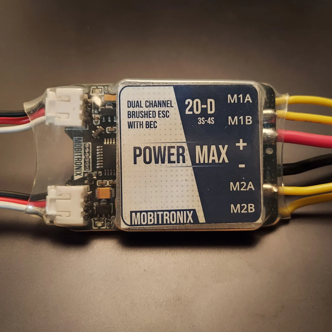
The Dual Channel Brushed ESC 20A (Manufacturer: Mobitronix, Part ID: PowerMax) is a high-performance electronic speed controller designed to control the speed and direction of two brushed DC motors. With a current rating of 20A per channel, this ESC is ideal for applications such as remote-controlled (RC) vehicles, drones, robotics, and other projects requiring precise motor control. Its dual-channel design allows independent control of two motors, making it a versatile choice for multi-motor systems.

Explore Projects Built with Dual Channel Brushed ESC 20A

Use Cirkit Designer to design, explore, and prototype these projects online. Some projects support real-time simulation. Click "Open Project" to start designing instantly!
Raspberry Pi-Controlled Drone with Brushless Motors and Camera Module
Image of ROV: A project utilizing Dual Channel Brushed ESC 20A in a practical application
This circuit is designed for a multi-motor application, likely a drone or a similar vehicle, featuring eight brushless motors controlled by two 4-in-1 electronic speed controllers (ESCs). The ESCs are powered by a 3s2p 18650 battery pack and interfaced with a Pixhawk flight controller for motor management. Additionally, the system includes a Raspberry Pi 4B for advanced processing and control, which is connected to a NoIR camera module and a cooling fan, and a power module to supply and monitor the power to the Pixhawk.
Cirkit Designer LogoOpen Project in Cirkit Designer
Quadcopter BLDC Motor Control System with Radio Receiver
Image of rc car: A project utilizing Dual Channel Brushed ESC 20A in a practical application
This circuit is designed to control four Brushless DC (BLDC) motors using corresponding Electronic Speed Controllers (ESCs). Each ESC receives power from a shared LiPo battery and control signals from an FS-CT6B receiver, which likely receives input from a remote transmitter for wireless control. The ESCs regulate the power supplied to the motors based on the received signals, enabling precise speed and direction control of the motors, typically used in applications such as drones or remote-controlled vehicles.
Cirkit Designer LogoOpen Project in Cirkit Designer
Wi-Fi Controlled Robotic System with ESP32-CAM and Brushless Motor
Image of RICKY BOT: A project utilizing Dual Channel Brushed ESC 20A in a practical application
This circuit is designed to control a brushless motor and two DC motors using an ESP32-CAM microcontroller. The Electronic Speed Controller (ESC) is powered by a LiPo battery and drives the brushless motor, while the L298N motor driver, powered by a 12V battery, controls the two DC motors. The ESP32-CAM provides control signals to both the ESC and the L298N motor driver.
Cirkit Designer LogoOpen Project in Cirkit Designer
Raspberry Pi and Pixhawk-Based Battery-Powered Drone with Brushless Motors
Image of Robotik: A project utilizing Dual Channel Brushed ESC 20A in a practical application
This circuit is designed to control multiple brushless motors using electronic speed controllers (ESCs) managed by a Pixhawk flight controller. The system is powered by a LiPo battery, and a Raspberry Pi 4B is used for additional processing and interfacing with a camera module. The ESCs receive power from the battery and control signals from the Pixhawk, which in turn communicates with the Raspberry Pi for telemetry and control purposes.
Cirkit Designer LogoOpen Project in Cirkit Designer

Explore Projects Built with Dual Channel Brushed ESC 20A

Use Cirkit Designer to design, explore, and prototype these projects online. Some projects support real-time simulation. Click "Open Project" to start designing instantly!
Image of ROV: A project utilizing Dual Channel Brushed ESC 20A in a practical application
Raspberry Pi-Controlled Drone with Brushless Motors and Camera Module
This circuit is designed for a multi-motor application, likely a drone or a similar vehicle, featuring eight brushless motors controlled by two 4-in-1 electronic speed controllers (ESCs). The ESCs are powered by a 3s2p 18650 battery pack and interfaced with a Pixhawk flight controller for motor management. Additionally, the system includes a Raspberry Pi 4B for advanced processing and control, which is connected to a NoIR camera module and a cooling fan, and a power module to supply and monitor the power to the Pixhawk.
Cirkit Designer LogoOpen Project in Cirkit Designer
Image of rc car: A project utilizing Dual Channel Brushed ESC 20A in a practical application
Quadcopter BLDC Motor Control System with Radio Receiver
This circuit is designed to control four Brushless DC (BLDC) motors using corresponding Electronic Speed Controllers (ESCs). Each ESC receives power from a shared LiPo battery and control signals from an FS-CT6B receiver, which likely receives input from a remote transmitter for wireless control. The ESCs regulate the power supplied to the motors based on the received signals, enabling precise speed and direction control of the motors, typically used in applications such as drones or remote-controlled vehicles.
Cirkit Designer LogoOpen Project in Cirkit Designer
Image of RICKY BOT: A project utilizing Dual Channel Brushed ESC 20A in a practical application
Wi-Fi Controlled Robotic System with ESP32-CAM and Brushless Motor
This circuit is designed to control a brushless motor and two DC motors using an ESP32-CAM microcontroller. The Electronic Speed Controller (ESC) is powered by a LiPo battery and drives the brushless motor, while the L298N motor driver, powered by a 12V battery, controls the two DC motors. The ESP32-CAM provides control signals to both the ESC and the L298N motor driver.
Cirkit Designer LogoOpen Project in Cirkit Designer
Image of Robotik: A project utilizing Dual Channel Brushed ESC 20A in a practical application
Raspberry Pi and Pixhawk-Based Battery-Powered Drone with Brushless Motors
This circuit is designed to control multiple brushless motors using electronic speed controllers (ESCs) managed by a Pixhawk flight controller. The system is powered by a LiPo battery, and a Raspberry Pi 4B is used for additional processing and interfacing with a camera module. The ESCs receive power from the battery and control signals from the Pixhawk, which in turn communicates with the Raspberry Pi for telemetry and control purposes.
Cirkit Designer LogoOpen Project in Cirkit Designer

Common Applications

  • RC cars, boats, and drones
  • Robotics and automation systems
  • DIY motorized projects
  • Educational and prototyping platforms

Technical Specifications

The following table outlines the key technical details of the Dual Channel Brushed ESC 20A:

Parameter Specification
Manufacturer Mobitronix
Part ID PowerMax
Motor Type Supported Brushed DC Motors
Channels 2 (independent control)
Continuous Current Rating 20A per channel
Peak Current Rating 25A per channel (for 10 seconds)
Input Voltage Range 6V to 24V DC
PWM Input Signal Range 1ms to 2ms (standard RC PWM signal)
Control Frequency 50Hz to 500Hz
Operating Temperature -10°C to 60°C
Dimensions 60mm x 40mm x 15mm
Weight 45g

Pin Configuration and Descriptions

The ESC has the following pin configuration:

Input/Output Connections

Pin Name Type Description
VIN Power Input Positive input voltage (6V to 24V DC). Connect to the power source.
GND Power Input Ground connection. Connect to the negative terminal of the power source.
M1+ Motor Output Positive terminal for Motor 1.
M1- Motor Output Negative terminal for Motor 1.
M2+ Motor Output Positive terminal for Motor 2.
M2- Motor Output Negative terminal for Motor 2.
PWM1 Signal Input PWM signal input for Motor 1 control.
PWM2 Signal Input PWM signal input for Motor 2 control.
EN Signal Input Enable pin. Pull HIGH to enable the ESC, LOW to disable it.

Usage Instructions

How to Use the Component in a Circuit

  1. Power Supply: Connect the VIN and GND pins to a DC power source within the range of 6V to 24V. Ensure the power source can supply sufficient current for the motors.
  2. Motor Connections: Connect the brushed DC motors to the M1+/M1- and M2+/M2- terminals. Ensure the motors are compatible with the ESC's voltage and current ratings.
  3. PWM Signal: Provide a PWM signal to the PWM1 and PWM2 pins to control the speed and direction of the motors. A 1ms pulse corresponds to full reverse, 1.5ms to stop, and 2ms to full forward.
  4. Enable Pin: Pull the EN pin HIGH to enable the ESC. Pull it LOW to disable the ESC.

Important Considerations and Best Practices

  • Heat Dissipation: Ensure proper ventilation or use a heatsink if the ESC operates near its maximum current rating for extended periods.
  • Power Supply: Use a power source with sufficient current capacity to avoid voltage drops or overheating.
  • Signal Integrity: Use shielded cables for PWM signals in noisy environments to prevent interference.
  • Motor Compatibility: Verify that the motors' voltage and current ratings are within the ESC's specifications.

Example: Using the ESC with an Arduino UNO

Below is an example of how to control the Dual Channel Brushed ESC 20A using an Arduino UNO:

// Example code to control the Dual Channel Brushed ESC 20A with Arduino UNO
#include <Servo.h> // Include the Servo library to generate PWM signals

Servo motor1; // Create a Servo object for Motor 1
Servo motor2; // Create a Servo object for Motor 2

void setup() {
  motor1.attach(9); // Attach Motor 1 PWM signal to pin 9
  motor2.attach(10); // Attach Motor 2 PWM signal to pin 10

  pinMode(8, OUTPUT); // Set pin 8 as output for the Enable pin
  digitalWrite(8, HIGH); // Enable the ESC by pulling the EN pin HIGH
}

void loop() {
  // Set Motor 1 to full forward
  motor1.writeMicroseconds(2000); // 2ms pulse for full forward
  delay(2000); // Run for 2 seconds

  // Set Motor 1 to stop
  motor1.writeMicroseconds(1500); // 1.5ms pulse to stop
  delay(2000); // Wait for 2 seconds

  // Set Motor 2 to full reverse
  motor2.writeMicroseconds(1000); // 1ms pulse for full reverse
  delay(2000); // Run for 2 seconds

  // Set Motor 2 to stop
  motor2.writeMicroseconds(1500); // 1.5ms pulse to stop
  delay(2000); // Wait for 2 seconds
}

Troubleshooting and FAQs

Common Issues and Solutions

  1. Motors Not Spinning

    • Cause: The EN pin is not pulled HIGH.
    • Solution: Ensure the EN pin is connected to a HIGH signal (e.g., 5V from the Arduino).
  2. Erratic Motor Behavior

    • Cause: Noisy or unstable PWM signal.
    • Solution: Use shielded cables for PWM signals and ensure the Arduino's ground is connected to the ESC's ground.
  3. Overheating

    • Cause: Operating near or above the ESC's current rating for extended periods.
    • Solution: Reduce the load on the motors or improve heat dissipation with a heatsink or fan.
  4. No Response from ESC

    • Cause: Incorrect wiring or insufficient power supply.
    • Solution: Double-check all connections and ensure the power supply meets the voltage and current requirements.

FAQs

  1. Can I use this ESC with a single motor?

    • Yes, you can use only one channel of the ESC if your application requires a single motor.
  2. What happens if I exceed the 20A current rating?

    • The ESC may overheat or shut down to protect itself. Prolonged overcurrent conditions can damage the ESC.
  3. Can I use this ESC with a LiPo battery?

    • Yes, as long as the battery voltage is within the 6V to 24V range.
  4. Is this ESC compatible with other microcontrollers?

    • Yes, it can be controlled by any microcontroller capable of generating a standard RC PWM signal.