How to Use Terminal Strip 2x5: Examples, Pinouts, and Specs
Introduction
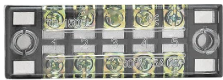
The Terminal Strip 2x5 is a versatile and compact electrical component designed for connecting multiple wires in a circuit. It features 10 connection points arranged in two rows of five, allowing for organized and secure wire connections. This component is commonly used in prototyping, industrial control panels, and general-purpose wiring applications. Its modular design makes it ideal for creating clean and reliable connections in both temporary and permanent setups.
Explore Projects Built with Terminal Strip 2x5


Explore Projects Built with Terminal Strip 2x5
Common Applications
- Prototyping and breadboarding circuits
- Industrial control systems
- Home automation wiring
- Audio and speaker connections
- Robotics and DIY electronics projects
Technical Specifications
The following table outlines the key technical details of the Terminal Strip 2x5:
| Parameter | Specification |
|---|---|
| Number of Terminals | 10 (2 rows of 5) |
| Terminal Type | Screw-type |
| Maximum Voltage | 300V AC/DC |
| Maximum Current | 15A |
| Wire Gauge Support | 22 AWG to 12 AWG |
| Material | Flame-retardant plastic (housing), |
| nickel-plated brass (terminals) | |
| Mounting Type | Panel mount or free-standing |
| Dimensions | 50mm x 20mm x 15mm |
| Operating Temperature | -40°C to 85°C |
Pin Configuration and Descriptions
The Terminal Strip 2x5 does not have traditional "pins" like an IC but instead features screw terminals for wire connections. Below is a description of the terminal layout:
| Terminal Number | Description |
|---|---|
| 1-5 (Row 1) | First row of screw terminals for wire |
| connections. Typically used for input. | |
| 6-10 (Row 2) | Second row of screw terminals for wire |
| connections. Typically used for output. |
Usage Instructions
How to Use the Terminal Strip 2x5 in a Circuit
- Prepare the Wires: Strip approximately 5-7mm of insulation from the ends of the wires you wish to connect.
- Insert the Wires: Loosen the screws on the desired terminals, insert the stripped wire ends into the terminal openings, and tighten the screws securely.
- Verify Connections: Ensure that the wires are firmly held in place and that there is no exposed copper outside the terminal.
- Mount the Terminal Strip (if needed): Use screws or adhesive to mount the terminal strip to a panel or enclosure for a more permanent setup.
Important Considerations and Best Practices
- Wire Gauge Compatibility: Ensure that the wires you are using fall within the supported range (22 AWG to 12 AWG).
- Avoid Over-tightening: Tighten the screws firmly but avoid over-tightening, as this may damage the terminal or the wire.
- Insulation Check: Double-check that no exposed wire is touching adjacent terminals to prevent short circuits.
- Current and Voltage Ratings: Do not exceed the maximum current (15A) or voltage (300V) ratings to avoid overheating or damage.
- Labeling: For complex circuits, consider labeling the terminals to keep track of connections.
Example: Connecting to an Arduino UNO
The Terminal Strip 2x5 can be used to organize connections between an Arduino UNO and external components. Below is an example of how to connect an LED and a resistor using the terminal strip:
- Connect one terminal of the resistor to the Arduino's digital pin (e.g., pin 13) via the terminal strip.
- Connect the other terminal of the resistor to the anode (+) of the LED via the terminal strip.
- Connect the cathode (-) of the LED to the Arduino's GND pin via the terminal strip.
Here is a simple Arduino code to blink the LED:
// Define the pin connected to the LED
const int ledPin = 13;

void setup() {
  pinMode(ledPin, OUTPUT); // Set the LED pin as an output
}

void loop() {
  digitalWrite(ledPin, HIGH); // Turn the LED on
  delay(1000);                // Wait for 1 second
  digitalWrite(ledPin, LOW);  // Turn the LED off
  delay(1000);                // Wait for 1 second
}
Troubleshooting and FAQs
Common Issues
Loose Connections: If a wire is not securely fastened, it may cause intermittent connections or circuit failure.
- Solution: Ensure that the screws are tightened properly and the wire is fully inserted into the terminal.
Short Circuits: Exposed wires touching adjacent terminals can lead to short circuits.
- Solution: Double-check all connections and ensure proper insulation.
Overheating: If the terminal strip becomes hot during operation, it may be due to excessive current.
- Solution: Verify that the current does not exceed the 15A rating and use appropriate wire gauges.
Corrosion or Oxidation: Over time, terminals may corrode, leading to poor conductivity.
- Solution: Use terminals with nickel-plated brass for better corrosion resistance and clean contacts periodically.
FAQs
Q: Can I use the Terminal Strip 2x5 for AC and DC circuits?
A: Yes, the terminal strip is suitable for both AC and DC circuits, provided the voltage and current ratings are not exceeded.
Q: How do I mount the terminal strip?
A: The terminal strip can be mounted using screws through the provided mounting holes or placed freely in your setup.
Q: Can I connect multiple wires to a single terminal?
A: While it is possible, it is not recommended as it may compromise the connection's reliability. Use one wire per terminal for best results.
Q: Is the terminal strip reusable?
A: Yes, the terminal strip can be reused multiple times. Simply loosen the screws to disconnect wires and re-tighten them for new connections.