How to Use RPM TACH Sensor: Examples, Pinouts, and Specs
Introduction
The RPM TACH Sensor, manufactured by RPM (Part ID: RPM), is a device designed to measure the rotational speed of an object, typically in revolutions per minute (RPM). This sensor is widely used in automotive, industrial, and mechanical systems to monitor engine performance, diagnose issues, and ensure optimal operation. Its ability to provide accurate and real-time RPM data makes it an essential component in applications requiring precise speed monitoring.
Explore Projects Built with RPM TACH Sensor
Explore Projects Built with RPM TACH Sensor
Common Applications and Use Cases
- Automotive engine RPM monitoring for performance tuning and diagnostics.
- Industrial machinery speed measurement and control.
- Robotics and automation systems requiring rotational speed feedback.
- Wind turbine and generator speed monitoring.
- Laboratory experiments and educational projects involving rotational systems.
Technical Specifications
The RPM TACH Sensor is designed for reliability and precision. Below are its key technical details:
General Specifications
| Parameter | Value |
|---|---|
| Manufacturer | RPM |
| Part ID | RPM |
| Measurement Range | 0 to 10,000 RPM |
| Output Signal Type | Digital (Pulse) |
| Supply Voltage | 5V to 24V DC |
| Output Voltage | 0V (Low) / Supply Voltage (High) |
| Operating Temperature | -20°C to 85°C |
| Sensor Type | Hall Effect or Optical (varies by model) |
| Response Time | < 1 ms |
Pin Configuration and Descriptions
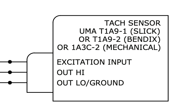
The RPM TACH Sensor typically comes with a 3-pin or 4-pin connector. Below is the pinout description:
3-Pin Configuration
| Pin Number | Name | Description |
|---|---|---|
| 1 | VCC | Power supply input (5V to 24V DC) |
| 2 | GND | Ground connection |
| 3 | Signal Out | Digital pulse output for RPM measurement |
4-Pin Configuration (Optional)
| Pin Number | Name | Description |
|---|---|---|
| 1 | VCC | Power supply input (5V to 24V DC) |
| 2 | GND | Ground connection |
| 3 | Signal Out | Digital pulse output for RPM measurement |
| 4 | Enable | Optional pin to enable/disable the sensor |
Usage Instructions
How to Use the RPM TACH Sensor in a Circuit
- Power the Sensor: Connect the VCC pin to a DC power source (5V to 24V) and the GND pin to the ground of the circuit.
- Connect the Signal Output: Attach the Signal Out pin to a microcontroller or frequency counter to read the pulse output.
- Read the Output: The sensor generates a digital pulse for each rotation of the monitored object. The frequency of the pulses corresponds to the RPM.
- Calculate RPM: Use the formula below to calculate RPM from the pulse frequency: [ \text{RPM} = \frac{\text{Frequency (Hz)} \times 60}{\text{Number of Pulses per Revolution}} ]
Important Considerations and Best Practices
- Ensure the sensor is aligned properly with the rotating object for accurate readings.
- Use pull-up or pull-down resistors on the Signal Out pin if required by your microcontroller.
- Avoid exposing the sensor to extreme temperatures or vibrations beyond its rated limits.
- For Hall Effect sensors, ensure the target object has a magnetic or ferrous surface.
- For optical sensors, keep the lens clean and free of obstructions.
Example: Connecting to an Arduino UNO
Below is an example of how to connect and use the RPM TACH Sensor with an Arduino UNO:
Circuit Connections
- VCC: Connect to the Arduino's 5V pin.
- GND: Connect to the Arduino's GND pin.
- Signal Out: Connect to Arduino digital pin 2.
Arduino Code
// RPM TACH Sensor Example Code for Arduino UNO
// Measures RPM using a digital pulse signal from the sensor

const int signalPin = 2;  // Pin connected to the sensor's Signal Out
volatile int pulseCount = 0;  // Variable to store pulse count
unsigned long lastTime = 0;   // Time of the last RPM calculation
const int pulsesPerRevolution = 1;  // Adjust based on your sensor's specs

void setup() {
  pinMode(signalPin, INPUT_PULLUP);  // Set signal pin as input with pull-up
  attachInterrupt(digitalPinToInterrupt(signalPin), countPulse, RISING);
  Serial.begin(9600);  // Initialize serial communication
}

void loop() {
  unsigned long currentTime = millis();
  if (currentTime - lastTime >= 1000) {  // Calculate RPM every second
    noInterrupts();  // Disable interrupts to safely access pulseCount
    int rpm = (pulseCount * 60) / pulsesPerRevolution;
    pulseCount = 0;  // Reset pulse count
    interrupts();  // Re-enable interrupts

    Serial.print("RPM: ");
    Serial.println(rpm);  // Print RPM to the Serial Monitor
    lastTime = currentTime;  // Update the last calculation time
  }
}

void countPulse() {
  pulseCount++;  // Increment pulse count on each rising edge
}
Troubleshooting and FAQs
Common Issues and Solutions
No Output Signal:
- Ensure the sensor is powered correctly (check VCC and GND connections).
- Verify the alignment of the sensor with the rotating object.
- Check for obstructions or dirt on the sensor (for optical models).
Inaccurate RPM Readings:
- Confirm the number of pulses per revolution matches the sensor's specifications.
- Use a stable power supply to avoid noise in the output signal.
- Ensure the microcontroller's interrupt pin is configured correctly.
Intermittent Signal Loss:
- Check for loose or damaged wiring.
- Ensure the sensor is not exposed to excessive vibrations or electromagnetic interference.
FAQs
Q: Can the RPM TACH Sensor measure speeds above 10,000 RPM?
A: No, the sensor is rated for a maximum of 10,000 RPM. Exceeding this limit may result in inaccurate readings or damage to the sensor.
Q: Is the sensor compatible with 3.3V microcontrollers?
A: Yes, but ensure the output signal voltage is within the input tolerance of the microcontroller. Use a voltage divider if necessary.
Q: How do I clean the sensor?
A: For optical sensors, use a soft, lint-free cloth to clean the lens. Avoid using abrasive materials or solvents.
Q: Can I use the sensor in outdoor environments?
A: The sensor is not waterproof. If outdoor use is required, ensure it is housed in a protective enclosure.