How to Use EC11: Examples, Pinouts, and Specs
Introduction
The EC11 is a rotary encoder, a type of electromechanical device that converts the angular position or motion of a shaft into an electrical signal. It is widely used for position sensing and control in various applications. Unlike potentiometers, rotary encoders can provide infinite rotation and are commonly employed in devices requiring precise adjustments, such as volume knobs, menu navigation controls, and joysticks.
Explore Projects Built with EC11
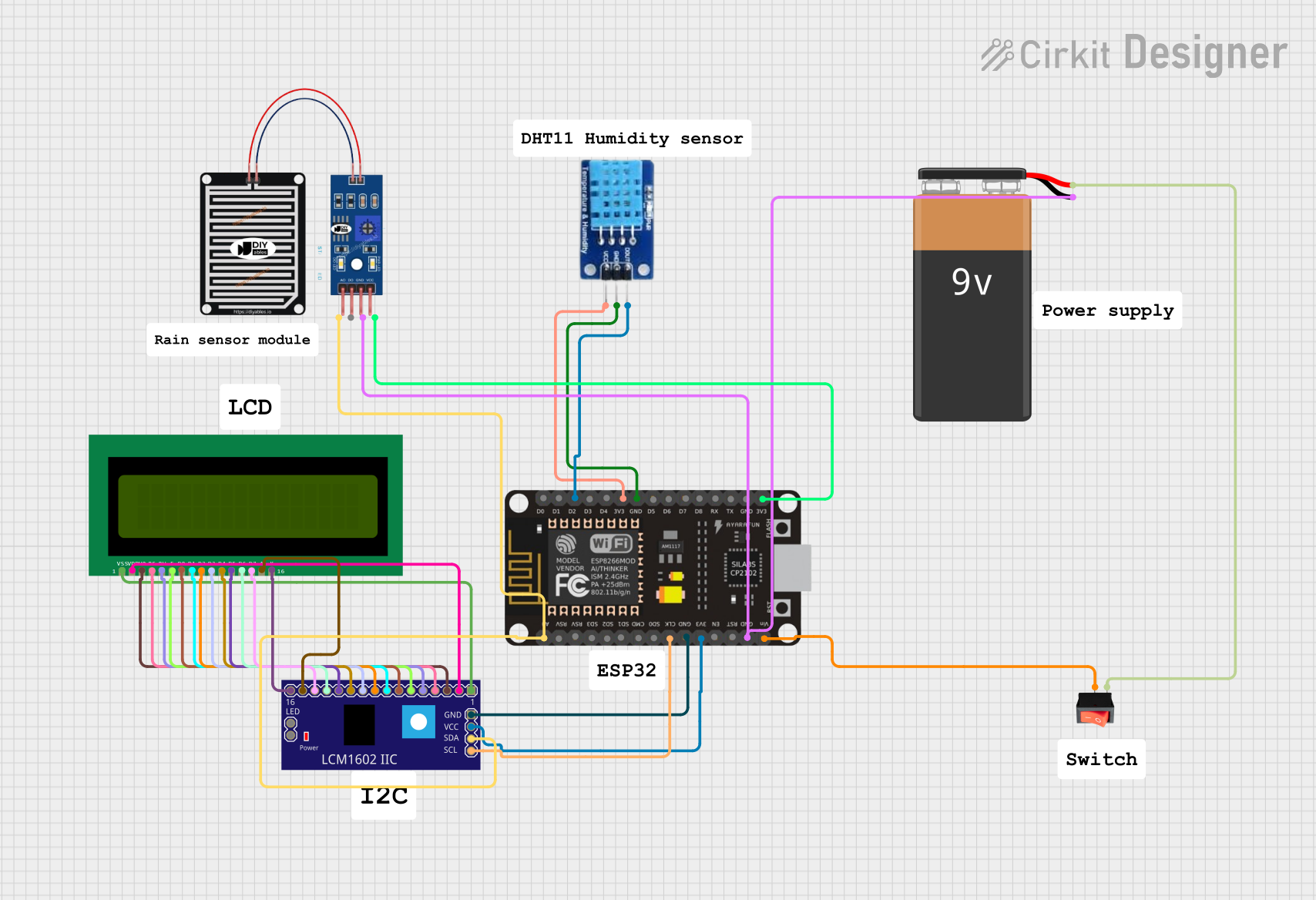
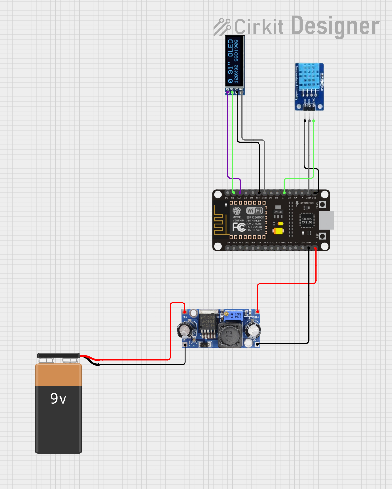
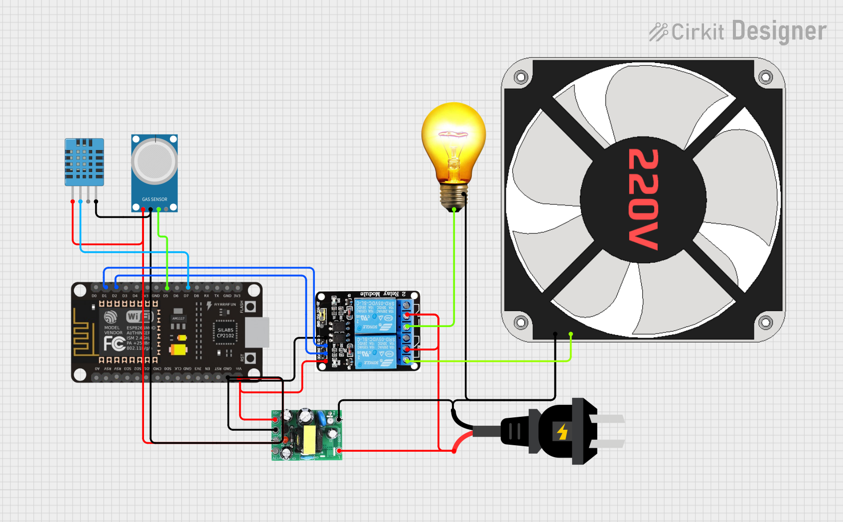
Explore Projects Built with EC11
Common Applications
- Volume control in audio equipment
- Menu navigation in embedded systems
- Position sensing in robotics
- User interface controls for industrial equipment
- Gaming joysticks and controllers
Technical Specifications
The EC11 rotary encoder is compact, durable, and designed for long-term use. Below are its key technical details:
| Parameter | Specification |
|---|---|
| Operating Voltage | 5V DC |
| Operating Current | 10 mA (typical) |
| Output Signal | Quadrature (A and B channels) |
| Resolution | 20 pulses per revolution (PPR) |
| Shaft Length | 15 mm |
| Shaft Diameter | 6 mm |
| Operating Temperature | -30°C to +70°C |
| Mechanical Life | 30,000 cycles |
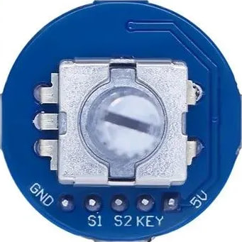
Pin Configuration
The EC11 typically has 5 pins, as described in the table below:
| Pin | Name | Description |
|---|---|---|
| 1 | GND | Ground connection |
| 2 | VCC | Power supply (typically 5V) |
| 3 | SW (Switch) | Push-button switch output (active low) |
| 4 | A (Channel A) | Quadrature output signal A (used for detecting rotation direction and position) |
| 5 | B (Channel B) | Quadrature output signal B (used for detecting rotation direction and position) |
Usage Instructions
How to Use the EC11 in a Circuit
- Power Connections: Connect the VCC pin to a 5V power source and the GND pin to ground.
- Signal Connections: Connect the A and B pins to the input pins of a microcontroller (e.g., Arduino) to read the quadrature signals.
- Switch Connection: If using the push-button feature, connect the SW pin to a digital input pin on the microcontroller. Use a pull-up resistor if necessary.
- Debouncing: Rotary encoders often produce noisy signals. Use hardware (capacitors) or software debouncing to ensure clean signal readings.
Important Considerations
- Pull-up Resistors: Use pull-up resistors on the A, B, and SW pins if they are not internally pulled up by the microcontroller.
- Debouncing: Implement software debouncing to filter out noise from the encoder's mechanical contacts.
- Signal Decoding: Use a microcontroller to decode the quadrature signals and determine the direction and position of rotation.
Example Code for Arduino UNO
Below is an example of how to use the EC11 rotary encoder with an Arduino UNO:
// EC11 Rotary Encoder Example Code for Arduino UNO
// Connect A to pin 2, B to pin 3, and SW to pin 4 on the Arduino

#define PIN_A 2  // Channel A pin
#define PIN_B 3  // Channel B pin
#define PIN_SW 4 // Push-button pin

volatile int encoderPosition = 0; // Tracks the encoder position
volatile bool aLastState;         // Last state of Channel A

void setup() {
  pinMode(PIN_A, INPUT_PULLUP); // Enable pull-up resistor for Channel A
  pinMode(PIN_B, INPUT_PULLUP); // Enable pull-up resistor for Channel B
  pinMode(PIN_SW, INPUT_PULLUP); // Enable pull-up resistor for Switch

  // Attach interrupt to Channel A for detecting rotation
  attachInterrupt(digitalPinToInterrupt(PIN_A), readEncoder, CHANGE);

  Serial.begin(9600); // Initialize serial communication
  aLastState = digitalRead(PIN_A); // Read initial state of Channel A
}

void loop() {
  // Check if the push-button is pressed
  if (digitalRead(PIN_SW) == LOW) {
    Serial.println("Button Pressed!");
    delay(200); // Debounce delay
  }

  // Print the encoder position
  Serial.print("Encoder Position: ");
  Serial.println(encoderPosition);
  delay(100); // Small delay for readability
}

// Interrupt service routine to read the encoder
void readEncoder() {
  bool aState = digitalRead(PIN_A); // Read current state of Channel A
  bool bState = digitalRead(PIN_B); // Read current state of Channel B

  // Determine rotation direction based on quadrature signals
  if (aState != aLastState) {
    if (bState != aState) {
      encoderPosition++; // Clockwise rotation
    } else {
      encoderPosition--; // Counterclockwise rotation
    }
  }
  aLastState = aState; // Update last state of Channel A
}
Notes:
- Ensure the encoder is securely mounted to avoid mechanical noise.
- Use capacitors (e.g., 0.1 µF) across the A and B pins to reduce electrical noise.
Troubleshooting and FAQs
Common Issues
No Signal Detected:
- Ensure the VCC and GND pins are properly connected.
- Verify that the A and B pins are connected to the correct microcontroller pins.
- Check for loose or faulty wiring.
Erratic or Noisy Readings:
- Add hardware debouncing (capacitors) or implement software debouncing.
- Ensure the encoder is not exposed to excessive vibration or mechanical stress.
Push-Button Not Working:
- Verify the SW pin connection and ensure a pull-up resistor is used.
- Check if the button is physically stuck or damaged.
FAQs
Q: Can the EC11 be used with 3.3V systems?
A: Yes, the EC11 can operate at 3.3V, but ensure the microcontroller's input pins are compatible with the encoder's output signals.
Q: How do I increase the resolution of the encoder?
A: The EC11 has a fixed resolution of 20 pulses per revolution. To achieve higher resolution, consider using a different encoder model with a higher PPR rating.
Q: Can I use the EC11 for high-speed applications?
A: The EC11 is suitable for low to moderate-speed applications. For high-speed applications, use an encoder designed for higher RPMs.
Q: How do I clean the encoder?
A: Use compressed air to remove dust. Avoid using liquids or solvents, as they may damage the internal components.
By following this documentation, you can effectively integrate the EC11 rotary encoder into your projects and troubleshoot common issues.