
How to Use JST XH Socket 4pin: Examples, Pinouts, and Specs
 Design with JST XH Socket 4pin in Cirkit Designer
Introduction
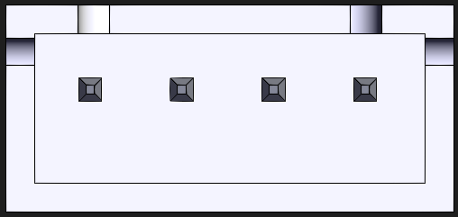
The JST XH Socket 4pin (Manufacturer Part ID: B4B-XH-AM) is a compact and reliable connector socket designed for secure electrical connections in a variety of electronic applications. Manufactured by JST, this 4-pin connector is widely used in consumer electronics, industrial equipment, and hobbyist projects due to its robust locking mechanism and ease of use. Its compact design makes it ideal for applications where space is limited, while its secure connection ensures stable performance.
Explore Projects Built with JST XH Socket 4pin
 Open Project in Cirkit Designer
 Open Project in Cirkit Designer
 Open Project in Cirkit Designer
 Open Project in Cirkit Designer
Explore Projects Built with JST XH Socket 4pin
Open Project in Cirkit DesignerOpen Project in Cirkit DesignerOpen Project in Cirkit DesignerOpen Project in Cirkit DesignerCommon Applications
- Battery connections in RC vehicles and drones
- Power and signal connections in small electronic devices
- Interfacing sensors and modules in embedded systems
- Wiring harnesses in industrial equipment
- Prototyping and DIY electronics projects
Technical Specifications
Key Technical Details
| Parameter | Specification |
|---|---|
| Manufacturer | JST |
| Part Number | B4B-XH-AM |
| Number of Pins | 4 |
| Pitch (Pin Spacing) | 2.5 mm |
| Rated Voltage | 250 V AC/DC |
| Rated Current | 3 A |
| Operating Temperature | -25°C to +85°C |
| Contact Resistance | ≤ 20 mΩ |
| Insulation Resistance | ≥ 1000 MΩ at 500 V DC |
| Material (Housing) | Polyamide (UL94V-0 flame-retardant) |
| Material (Contacts) | Tin-plated copper alloy |
Pin Configuration and Descriptions
The JST XH Socket 4pin has four pins arranged in a single row with a 2.5 mm pitch. Below is the pin configuration:
| Pin Number | Description | Typical Use Case |
|---|---|---|
| 1 | VCC (Power Supply) | Positive voltage input |
| 2 | GND (Ground) | Ground connection |
| 3 | Signal/Data Line 1 | Data or signal transmission line |
| 4 | Signal/Data Line 2 | Data or signal transmission line |
Usage Instructions
How to Use the JST XH Socket 4pin in a Circuit
- Connector Assembly:
- Use the corresponding JST XH 4-pin header or plug to mate with the socket.
- Ensure proper crimping of wires to the connector terminals using a crimping tool.
- Wiring:
- Connect the wires to the appropriate pins based on the pin configuration table.
- Double-check the polarity and signal connections to avoid damage to the circuit.
- Mounting:
- Secure the socket on a PCB or chassis using its through-hole or surface-mount design.
- Ensure the connector is firmly locked to prevent accidental disconnection.
- Testing:
- Verify the connections using a multimeter before powering the circuit.
- Check for continuity and proper voltage levels at each pin.
Important Considerations and Best Practices
- Avoid Overcurrent: Do not exceed the rated current of 3 A to prevent overheating or damage.
- Proper Crimping: Use the recommended crimping tool for JST XH terminals to ensure a secure and reliable connection.
- Secure Locking: Ensure the connector is fully inserted and locked to avoid intermittent connections.
- Environmental Conditions: Operate the socket within the specified temperature range (-25°C to +85°C) for optimal performance.
- Polarity Check: Always verify the polarity of the power and ground connections to prevent damage to connected devices.
Example: Connecting to an Arduino UNO
The JST XH Socket 4pin can be used to connect sensors or modules to an Arduino UNO. Below is an example of connecting a sensor with a JST XH 4-pin connector to the Arduino:
// Example: Reading data from a sensor connected via JST XH 4-pin socket
// Pin 1: VCC (5V), Pin 2: GND, Pin 3: Data Line 1 (Sensor Output),
// Pin 4: Data Line 2 (Optional or unused in this example)

const int sensorPin = A0; // Connect Data Line 1 to Arduino analog pin A0
int sensorValue = 0;      // Variable to store sensor reading

void setup() {
  Serial.begin(9600); // Initialize serial communication
  pinMode(sensorPin, INPUT); // Set sensor pin as input
}

void loop() {
  sensorValue = analogRead(sensorPin); // Read sensor value
  Serial.print("Sensor Value: ");
  Serial.println(sensorValue); // Print sensor value to Serial Monitor
  delay(500); // Wait for 500ms before next reading
}
Troubleshooting and FAQs
Common Issues and Solutions
| Issue | Possible Cause | Solution |
|---|---|---|
| Loose connection | Connector not fully inserted | Ensure the connector is securely locked. |
| No power or signal transmission | Incorrect wiring or polarity | Verify wiring and polarity using a multimeter. |
| Overheating of connector | Exceeding current rating | Reduce the load to within the 3 A limit. |
| Intermittent connection | Poor crimping of wires | Re-crimp the wires using the correct tool. |
FAQs
Q: Can the JST XH Socket 4pin handle high-frequency signals?
A: Yes, the socket can handle high-frequency signals, but ensure proper shielding and grounding in your circuit to minimize noise.
Q: Is the JST XH Socket 4pin compatible with other JST series connectors?
A: No, the JST XH series has a specific pitch (2.5 mm) and design. It is not directly compatible with other JST series like PH or SH.
Q: Can I use this connector for power delivery in a high-power application?
A: The connector is rated for a maximum current of 3 A. For higher power applications, consider using connectors with higher current ratings.
Q: How do I remove the connector without damaging it?
A: Press the locking tab gently while pulling the connector straight out to avoid bending the pins or damaging the housing.