Cirkit Designer Logo
Cirkit Designer
Your all-in-one circuit design IDE
Home / 
Component Documentation

How to Use CJMCU 6701: Examples, Pinouts, and Specs

Image of CJMCU 6701
Cirkit Designer LogoDesign with CJMCU 6701 in Cirkit Designer

Introduction

The CJMCU 6701 is a compact, high-performance accelerometer sensor module designed for motion detection, orientation sensing, and vibration monitoring in a wide range of applications. This versatile sensor is commonly used in mobile devices, gaming systems, robotics, and other embedded systems where accurate motion sensing is required.

Explore Projects Built with CJMCU 6701

Use Cirkit Designer to design, explore, and prototype these projects online. Some projects support real-time simulation. Click "Open Project" to start designing instantly!
Battery-Powered Emergency Alert System with NUCLEO-F072RB, SIM800L, and GPS NEO 6M
Image of women safety: A project utilizing CJMCU 6701 in a practical application
This circuit is an emergency alert system that uses a NUCLEO-F072RB microcontroller to send SMS alerts and make calls via a SIM800L GSM module, while obtaining location data from a GPS NEO 6M module. The system is powered by a Li-ion battery and includes a TP4056 module for battery charging and protection, with a rocker switch to control power to the microcontroller.
Cirkit Designer LogoOpen Project in Cirkit Designer
Arduino Pro Mini-Based Bluetooth and Camera-Controlled Motor System
Image of HAND GESTURE CAR: A project utilizing CJMCU 6701 in a practical application
This circuit is a remote-controlled robotic system featuring an Arduino Pro Mini, a TB6612FNG motor driver, and an NRF24L01 wireless module. The Arduino controls four DC motors via the motor driver and communicates wirelessly using the NRF24L01 module, while an OV7670 camera module and an HC-05 Bluetooth module provide additional functionality.
Cirkit Designer LogoOpen Project in Cirkit Designer
ESP8266 and SIM800L Based GPS Tracker with I2C LCD Display and Battery Power
Image of Little Innovator Competition: A project utilizing CJMCU 6701 in a practical application
This circuit integrates an ESP8266 NodeMCU microcontroller with a SIM800L GSM module, a GPS NEO 6M module, and a 16x2 I2C LCD display for communication and location tracking. It also includes a pushbutton for user input, a piezo buzzer for audio alerts, and is powered by a 2x 18650 battery pack through an LM2596 step-down module.
Cirkit Designer LogoOpen Project in Cirkit Designer
Arduino Mega 2560 Based Security System with Fingerprint Authentication and SMS Alerts
Image of Door security system: A project utilizing CJMCU 6701 in a practical application
This circuit features an Arduino Mega 2560 microcontroller interfaced with a SIM800L GSM module, two fingerprint scanners, an I2C LCD display, an IR sensor, and a piezo buzzer. Power management is handled by a PowerBoost 1000 Basic Pad USB, a TP4056 charging module, and a Li-ion 18650 battery, with an option to use a Mini AC-DC 110V-230V to 5V 700mA module for direct power supply. The primary functionality appears to be a security system with GSM communication capabilities, biometric access control, and visual/audible feedback.
Cirkit Designer LogoOpen Project in Cirkit Designer

Explore Projects Built with CJMCU 6701

Use Cirkit Designer to design, explore, and prototype these projects online. Some projects support real-time simulation. Click "Open Project" to start designing instantly!
Image of women safety: A project utilizing CJMCU 6701 in a practical application
Battery-Powered Emergency Alert System with NUCLEO-F072RB, SIM800L, and GPS NEO 6M
This circuit is an emergency alert system that uses a NUCLEO-F072RB microcontroller to send SMS alerts and make calls via a SIM800L GSM module, while obtaining location data from a GPS NEO 6M module. The system is powered by a Li-ion battery and includes a TP4056 module for battery charging and protection, with a rocker switch to control power to the microcontroller.
Cirkit Designer LogoOpen Project in Cirkit Designer
Image of HAND GESTURE CAR: A project utilizing CJMCU 6701 in a practical application
Arduino Pro Mini-Based Bluetooth and Camera-Controlled Motor System
This circuit is a remote-controlled robotic system featuring an Arduino Pro Mini, a TB6612FNG motor driver, and an NRF24L01 wireless module. The Arduino controls four DC motors via the motor driver and communicates wirelessly using the NRF24L01 module, while an OV7670 camera module and an HC-05 Bluetooth module provide additional functionality.
Cirkit Designer LogoOpen Project in Cirkit Designer
Image of Little Innovator Competition: A project utilizing CJMCU 6701 in a practical application
ESP8266 and SIM800L Based GPS Tracker with I2C LCD Display and Battery Power
This circuit integrates an ESP8266 NodeMCU microcontroller with a SIM800L GSM module, a GPS NEO 6M module, and a 16x2 I2C LCD display for communication and location tracking. It also includes a pushbutton for user input, a piezo buzzer for audio alerts, and is powered by a 2x 18650 battery pack through an LM2596 step-down module.
Cirkit Designer LogoOpen Project in Cirkit Designer
Image of Door security system: A project utilizing CJMCU 6701 in a practical application
Arduino Mega 2560 Based Security System with Fingerprint Authentication and SMS Alerts
This circuit features an Arduino Mega 2560 microcontroller interfaced with a SIM800L GSM module, two fingerprint scanners, an I2C LCD display, an IR sensor, and a piezo buzzer. Power management is handled by a PowerBoost 1000 Basic Pad USB, a TP4056 charging module, and a Li-ion 18650 battery, with an option to use a Mini AC-DC 110V-230V to 5V 700mA module for direct power supply. The primary functionality appears to be a security system with GSM communication capabilities, biometric access control, and visual/audible feedback.
Cirkit Designer LogoOpen Project in Cirkit Designer

Common Applications and Use Cases

  • Mobile and handheld devices for screen orientation
  • Gaming controllers for motion control
  • Robotics for movement and balance control
  • Vehicle dynamics monitoring
  • Activity tracking and sports analysis
  • Vibration analysis and machinery monitoring

Technical Specifications

Key Technical Details

  • Operating Voltage: 2.0V to 3.6V
  • Sensitivity: Selectable (typically ±2g/±4g/±8g/±16g)
  • Output: Digital (I2C/SPI)
  • Operating Temperature Range: -40°C to +85°C
  • Dimensions: 3mm x 3mm x 1mm (typical)

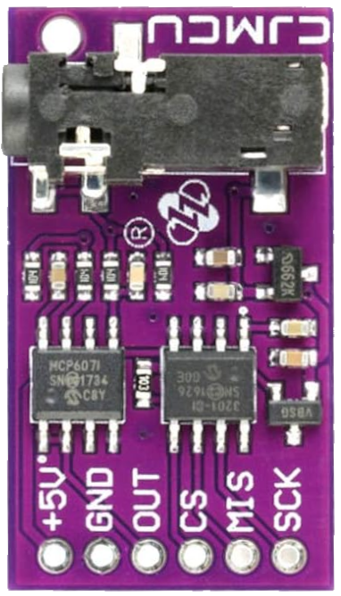
Pin Configuration and Descriptions

Pin Number Pin Name Description
1 VCC Power supply (2.0V to 3.6V)
2 GND Ground
3 SCL Serial Clock Line (I2C mode)
4 SDA Serial Data Line (I2C mode)
5 CS Chip Select (SPI mode)
6 SDO Serial Data Out (SPI mode)
7 SDI Serial Data In (SPI mode)
8 INT Interrupt output (active high or low)

Usage Instructions

How to Use the Component in a Circuit

  1. Power Supply: Connect the VCC pin to a 2.0V to 3.6V power source and the GND pin to the ground.
  2. Communication: Choose between I2C or SPI for communication with a microcontroller:
    • For I2C, connect SCL to the I2C clock line and SDA to the I2C data line.
    • For SPI, connect CS to the chip select, SDO to the MISO (Master In Slave Out), and SDI to the MOSI (Master Out Slave In) of the microcontroller.
  3. Interrupts (Optional): The INT pin can be connected to an interrupt-capable GPIO pin on the microcontroller to handle events like motion detection or free-fall.

Important Considerations and Best Practices

  • Ensure that the power supply is stable and within the specified voltage range to prevent damage to the sensor.
  • Use pull-up resistors on the I2C lines if they are not already present on the microcontroller board.
  • When using SPI, ensure that the CS pin is toggled correctly to enable and disable communication with the sensor.
  • Place the sensor away from sources of heat and electromagnetic interference to ensure accurate readings.
  • For precise measurements, calibrate the sensor in the application environment.

Example Code for Arduino UNO

#include <Wire.h>

// CJMCU 6701 I2C address (assuming A0 is grounded)
#define ACCEL_I2C_ADDR 0x18

void setup() {
  Wire.begin(); // Initialize I2C
  Serial.begin(9600); // Start serial communication at 9600 baud

  // Initialize CJMCU 6701
  Wire.beginTransmission(ACCEL_I2C_ADDR);
  // Add initialization code specific to the CJMCU 6701
  Wire.endTransmission();
}

void loop() {
  // Read acceleration data from CJMCU 6701
  Wire.beginTransmission(ACCEL_I2C_ADDR);
  // Add code to request data from the sensor
  Wire.endTransmission();
  Wire.requestFrom(ACCEL_I2C_ADDR, 6); // Request 6 bytes of data

  // Assuming the sensor sends back x, y, and z acceleration data
  if (Wire.available() == 6) {
    int xAccl = Wire.read() | Wire.read() << 8;
    int yAccl = Wire.read() | Wire.read() << 8;
    int zAccl = Wire.read() | Wire.read() << 8;

    // Process and output the acceleration data
    Serial.print("X: ");
    Serial.print(xAccl);
    Serial.print(" Y: ");
    Serial.print(yAccl);
    Serial.print(" Z: ");
    Serial.println(zAccl);
  }

  delay(100); // Delay for a short period before reading again
}

Troubleshooting and FAQs

Common Issues Users Might Face

  • No Data or Erratic Readings: Ensure that the connections are secure and the power supply is within the specified range. Check for proper pull-up resistors on the I2C lines.
  • Inaccurate Readings: Calibrate the sensor for the specific application environment and verify that the sensitivity settings are correct.
  • Communication Failure: Confirm that the correct communication protocol (I2C/SPI) is selected and that the microcontroller pins are configured properly.

Solutions and Tips for Troubleshooting

  • Double-check wiring and solder joints for any loose connections or shorts.
  • Use a logic analyzer or oscilloscope to verify the communication signals on the I2C/SPI lines.
  • Reset the power to the sensor module to clear any potential latch-up conditions.
  • Consult the sensor's datasheet for detailed operational characteristics and advanced configuration settings.

FAQs

Q: Can the CJMCU 6701 measure rotation? A: No, the CJMCU 6701 is an accelerometer and measures linear acceleration. For rotation, you would need a gyroscope sensor.

Q: How do I change the sensitivity of the sensor? A: Sensitivity can typically be adjusted through configuration registers. Refer to the sensor's datasheet for the specific register settings.

Q: What is the purpose of the INT pin? A: The INT pin can be used to trigger an interrupt in the microcontroller when certain conditions are met, such as threshold crossing or motion detection, allowing for event-driven processing.

Q: Is the CJMCU 6701 suitable for outdoor applications? A: While the CJMCU 6701 can operate in a wide temperature range, it should be protected from the elements (moisture, dust, etc.) to ensure longevity and reliability. Use an appropriate enclosure if necessary.