How to Use Pilot Lamp Red: Examples, Pinouts, and Specs
Introduction
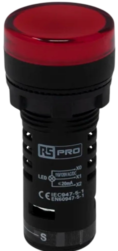
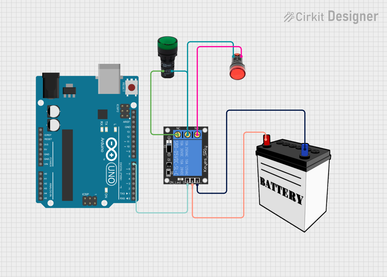
A Pilot Lamp Red is an electronic component that serves as a visual indicator, emitting a red light when powered. It is commonly used in control panels, dashboards, and electronic devices to signal power status, alert conditions, or as a warning indicator. Its bright red illumination is easily noticeable, making it an essential component in safety-critical applications.
Explore Projects Built with Pilot Lamp Red
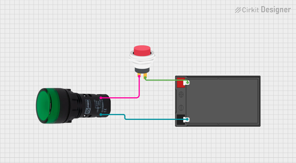
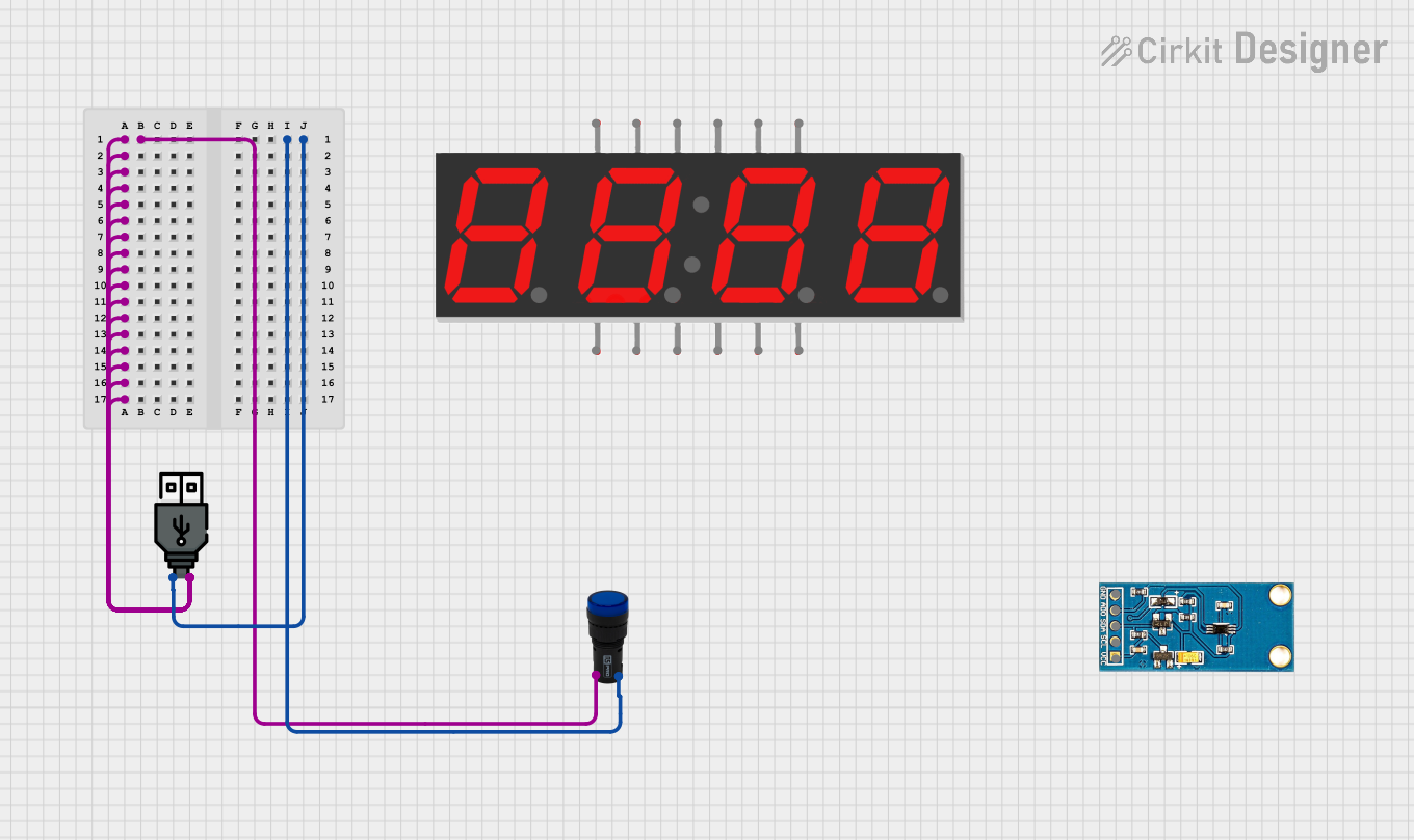
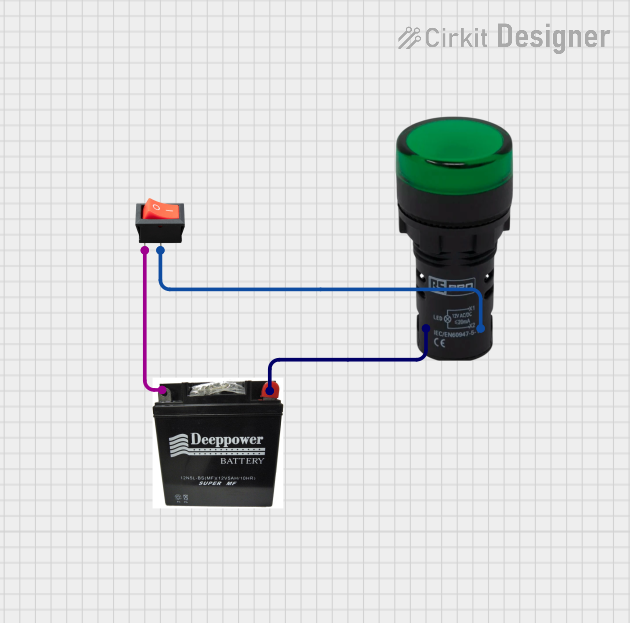
Explore Projects Built with Pilot Lamp Red
Common Applications and Use Cases
- Power status indicator on machinery and electronic devices
- Warning light for malfunction or abnormal operation
- Safety indicator on control panels and dashboards
- Signal light in automation systems
Technical Specifications
Key Technical Details
- Operating Voltage: Typically 2V to 24V (depending on model)
- Current Consumption: 10mA to 20mA (may vary)
- Power Ratings: Low power, usually less than 0.5W
- Luminous Intensity: Dependent on the specific lamp design
- Lifespan: Typically > 20,000 hours
- Operating Temperature: -20°C to +80°C
Pin Configuration and Descriptions
| Pin Number | Description |
|---|---|
| 1 | Anode (+) |
| 2 | Cathode (-) |
Usage Instructions
How to Use the Pilot Lamp Red in a Circuit
- Identify the Voltage Rating: Ensure the pilot lamp's voltage rating matches the circuit's supply voltage.
- Connect the Anode: Connect the anode (positive) pin of the Pilot Lamp Red to the positive side of the power supply, typically through a current-limiting resistor.
- Connect the Cathode: Connect the cathode (negative) pin to the ground or negative side of the power supply.
- Current-Limiting Resistor: Calculate and connect an appropriate resistor in series with the lamp to prevent excessive current flow that could damage the lamp.
Important Considerations and Best Practices
- Resistor Calculation: Use Ohm's Law to calculate the resistor value: ( R = \frac{V_{supply} - V_{lamp}}{I} )
- Polarity: Ensure correct polarity when connecting the lamp, as reversing the polarity will prevent the lamp from illuminating.
- Mounting: Secure the lamp in a panel or enclosure with appropriate mounting hardware.
- Heat Dissipation: Although Pilot Lamps typically generate minimal heat, ensure there is adequate ventilation around the lamp in enclosed spaces.
Troubleshooting and FAQs
Common Issues
- Lamp Does Not Illuminate: Check for correct polarity, proper voltage supply, and intact connections. Ensure the current-limiting resistor is correctly calculated and installed.
- Dim Light: Verify that the supply voltage matches the lamp's voltage rating. A lower voltage will result in dimmer light.
- Flickering Light: Inspect for loose connections or intermittent power supply. Also, check for any damage to the lamp itself.
Solutions and Tips for Troubleshooting
- Double-Check Connections: Revisit all connections to ensure they are secure and correct.
- Resistor Value: Recalculate the resistor value to confirm it is suitable for the supply voltage and lamp's current rating.
- Voltage Measurement: Use a multimeter to measure the voltage across the lamp to ensure it is within the specified range.
FAQs
Q: Can I use the Pilot Lamp Red with an Arduino UNO? A: Yes, you can connect the Pilot Lamp Red to an Arduino UNO using a digital output pin and a suitable current-limiting resistor.
Q: What happens if I reverse the polarity of the Pilot Lamp Red? A: The lamp will not light up if the polarity is reversed. Ensure the anode is connected to the positive supply and the cathode to the negative.
Q: How do I choose the correct current-limiting resistor? A: Calculate the resistor value based on the supply voltage, the lamp's voltage rating, and the desired current using Ohm's Law.
Example Arduino UNO Code
// Define the Arduino pin connected to the Pilot Lamp Red
const int pilotLampPin = 13; // Using onboard LED pin as an example

void setup() {
  // Set the pilot lamp pin as an output
  pinMode(pilotLampPin, OUTPUT);
}

void loop() {
  // Turn on the Pilot Lamp Red
  digitalWrite(pilotLampPin, HIGH);
  delay(1000); // Keep the lamp on for 1 second

  // Turn off the Pilot Lamp Red
  digitalWrite(pilotLampPin, LOW);
  delay(1000); // Keep the lamp off for 1 second
}
Note: When connecting the Pilot Lamp Red to an Arduino, ensure you use a current-limiting resistor in series with the lamp to prevent damage to both the lamp and the Arduino pin. The value of the resistor can be calculated using the formula provided in the "Important Considerations and Best Practices" section.