
How to Use ESP32-S3-N16R8: Examples, Pinouts, and Specs
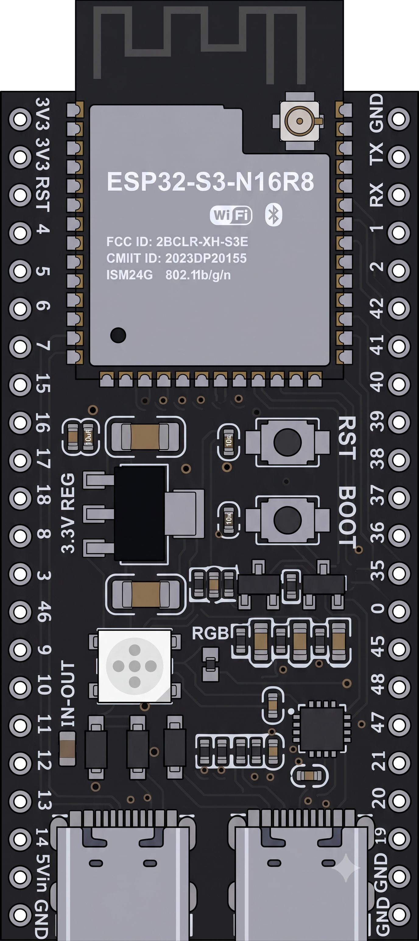
 Design with ESP32-S3-N16R8 in Cirkit Designer
Introduction
The ESP32-S3-N16R8, manufactured by Espressif Systems, is a high-performance microcontroller designed for IoT (Internet of Things) applications and advanced processing tasks. It features a dual-core processor, integrated Wi-Fi and Bluetooth connectivity, 16MB of flash memory, and 8MB of RAM. This versatile microcontroller is ideal for applications requiring high computational power, low power consumption, and seamless wireless communication.
Explore Projects Built with ESP32-S3-N16R8
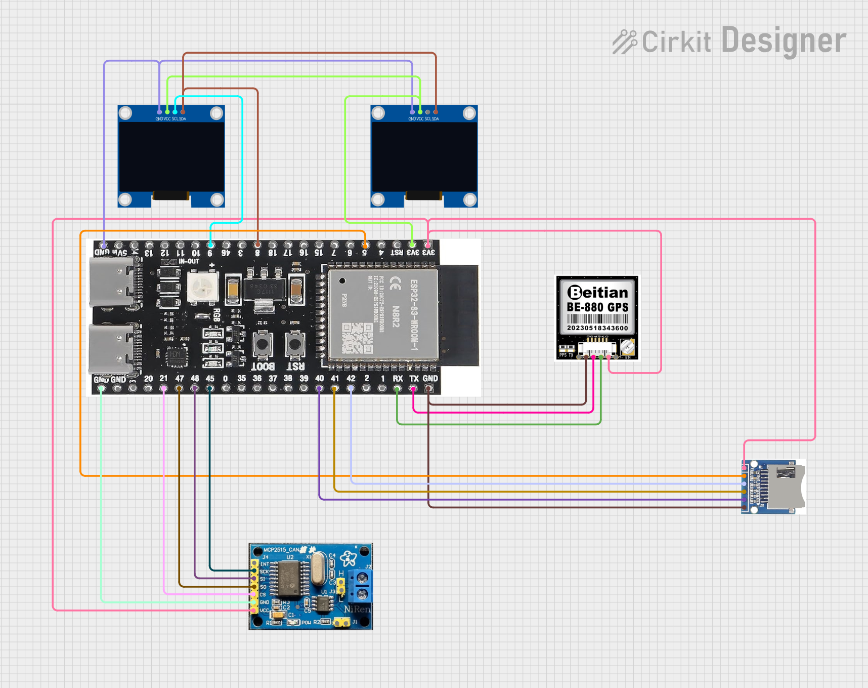 Open Project in Cirkit Designer
 Open Project in Cirkit Designer
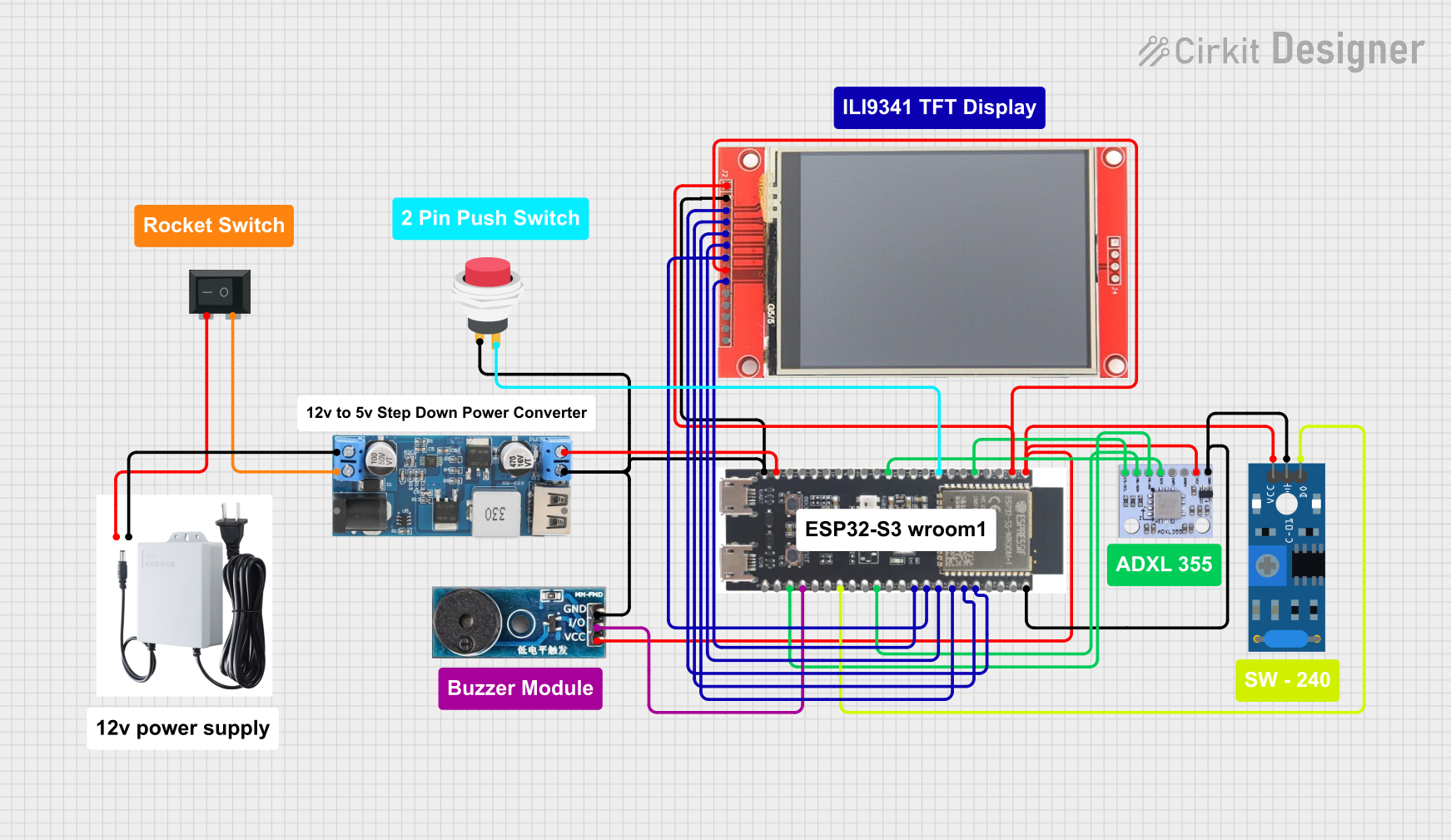 Open Project in Cirkit Designer
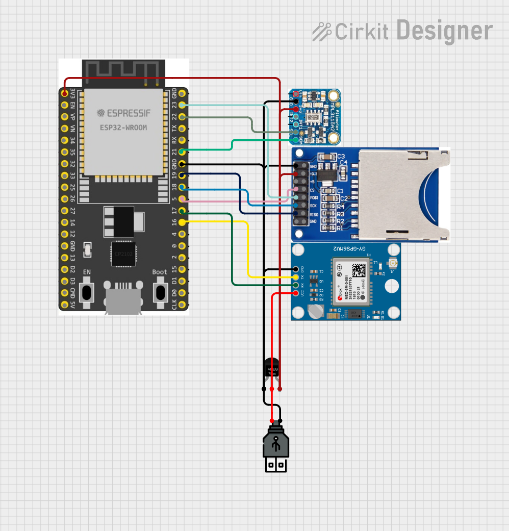 Open Project in Cirkit Designer
Explore Projects Built with ESP32-S3-N16R8
Open Project in Cirkit DesignerOpen Project in Cirkit DesignerOpen Project in Cirkit DesignerOpen Project in Cirkit DesignerCommon Applications and Use Cases
- Smart home devices (e.g., smart lights, thermostats, and security systems)
- Wearable technology
- Industrial IoT systems
- Edge computing and AI/ML applications
- Wireless sensor networks
- Robotics and automation
- Audio processing and streaming
Technical Specifications
Key Technical Details
| Parameter | Specification |
|---|---|
| Processor | Dual-core Xtensa® LX7 @ up to 240 MHz |
| Flash Memory | 16MB |
| RAM | 8MB |
| Wireless Connectivity | Wi-Fi 802.11 b/g/n (2.4 GHz), Bluetooth 5.0 LE |
| GPIO Pins | Up to 45 GPIOs |
| Operating Voltage | 3.0V to 3.6V |
| Power Consumption | Ultra-low power modes available |
| Interfaces | SPI, I2C, I2S, UART, ADC, DAC, PWM, USB OTG |
| Security Features | AES, SHA, RSA, HMAC, Digital Signature, Secure Boot |
| Operating Temperature | -40°C to +85°C |
| Package | QFN48 (7x7 mm) |
Pin Configuration and Descriptions
The ESP32-S3-N16R8 has a flexible pinout with up to 45 GPIOs. Below is a summary of key pins:
| Pin Name | Functionality | Description |
|---|---|---|
| GPIO0 | Boot Mode Selection, GPIO | Used for boot mode selection during startup |
| GPIO1-45 | General Purpose I/O | Configurable for digital I/O, ADC, PWM, etc. |
| EN | Chip Enable | Active high; enables the chip |
| 3V3 | Power Supply | 3.3V input for powering the chip |
| GND | Ground | Ground connection |
| TXD0/RXD0 | UART0 (Default Serial) | UART communication pins |
| USB_D+/D- | USB OTG | USB data lines for programming or peripherals |
| ADC1/ADC2 | Analog-to-Digital Converter Channels | Up to 20 ADC channels |
| DAC1/DAC2 | Digital-to-Analog Converter Channels | 2 DAC channels for analog output |
For a complete pinout, refer to the official datasheet provided by Espressif Systems.
Usage Instructions
How to Use the ESP32-S3-N16R8 in a Circuit
- Power Supply: Provide a stable 3.3V power supply to the
3V3pin and connectGNDto ground. - Boot Mode: Connect GPIO0 to ground during startup to enter bootloader mode for programming.
- Programming: Use the USB OTG interface or UART pins (TXD0/RXD0) to upload firmware.
- GPIO Configuration: Configure GPIO pins as needed for digital I/O, ADC, PWM, or other functions.
- Wireless Connectivity: Use the integrated Wi-Fi and Bluetooth modules for wireless communication.
Important Considerations and Best Practices
- Power Supply: Ensure a clean and stable 3.3V power source to avoid instability.
- GPIO Voltage Levels: Do not exceed 3.3V on GPIO pins to prevent damage.
- Antenna Placement: For optimal wireless performance, ensure the onboard antenna is not obstructed by metal or other RF-blocking materials.
- Heat Management: If operating at high loads, consider adding a heatsink or ensuring proper ventilation.
- Firmware Updates: Use Espressif's official tools (e.g.,
esptool.py) for firmware flashing and updates.
Example Code for Arduino UNO Integration
The ESP32-S3-N16R8 can be programmed using the Arduino IDE. Below is an example of connecting the ESP32-S3-N16R8 to a Wi-Fi network and toggling an LED:
#include <WiFi.h> // Include the Wi-Fi library

// Replace with your network credentials
const char* ssid = "Your_SSID";
const char* password = "Your_PASSWORD";

const int ledPin = 2; // GPIO2 is connected to an LED

void setup() {
  pinMode(ledPin, OUTPUT); // Set GPIO2 as an output
  Serial.begin(115200);    // Start serial communication

  // Connect to Wi-Fi
  Serial.print("Connecting to Wi-Fi");
  WiFi.begin(ssid, password);
  while (WiFi.status() != WL_CONNECTED) {
    delay(500);
    Serial.print(".");
  }
  Serial.println("\nWi-Fi connected!");
  Serial.print("IP Address: ");
  Serial.println(WiFi.localIP());
}

void loop() {
  digitalWrite(ledPin, HIGH); // Turn the LED on
  delay(1000);                // Wait for 1 second
  digitalWrite(ledPin, LOW);  // Turn the LED off
  delay(1000);                // Wait for 1 second
}
Notes:
- Install the ESP32 board package in the Arduino IDE before uploading the code.
- Ensure the correct board and port are selected in the Arduino IDE.
Troubleshooting and FAQs
Common Issues and Solutions
ESP32-S3-N16R8 Not Detected by PC:
- Ensure the USB cable is functional and supports data transfer.
- Check if the device is in bootloader mode (GPIO0 connected to GND during reset).
Wi-Fi Connection Fails:
- Verify the SSID and password are correct.
- Ensure the Wi-Fi network operates on the 2.4 GHz band (not 5 GHz).
GPIO Pins Not Responding:
- Confirm the pins are correctly configured in the code.
- Check for short circuits or incorrect voltage levels.
Overheating:
- Reduce the processing load or ensure proper ventilation.
- Verify the power supply voltage is within the recommended range.
FAQs
Q: Can the ESP32-S3-N16R8 operate on battery power?
A: Yes, it can operate on battery power, but ensure the battery provides a stable 3.3V output.
Q: How do I reset the ESP32-S3-N16R8?
A: Press the EN (enable) button on the development board or toggle the EN pin.
Q: Does the ESP32-S3-N16R8 support OTA (Over-the-Air) updates?
A: Yes, OTA updates are supported. You can implement OTA functionality using the Arduino IDE or Espressif's SDK.
Q: Can I use the ESP32-S3-N16R8 for AI/ML tasks?
A: Yes, the ESP32-S3-N16R8 supports AI/ML frameworks like TensorFlow Lite Micro for edge computing applications.