How to Use Placa de distribucion de Energia PDB XT60: Examples, Pinouts, and Specs
Introduction
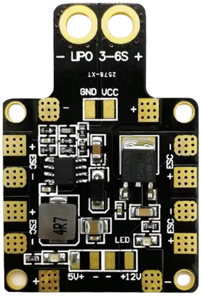
The Placa de Distribución de Energía PDB XT60 is a Power Distribution Board designed to efficiently distribute power from a single battery source to multiple electronic components in a circuit. Equipped with an XT60 connector for secure and reliable battery connections, this PDB is commonly used in applications requiring centralized power management, such as drones, RC vehicles, robotics, and other multi-component electronic systems.
Explore Projects Built with Placa de distribucion de Energia PDB XT60


Explore Projects Built with Placa de distribucion de Energia PDB XT60
Common Applications and Use Cases
- Drones and UAVs: Distributes power to motors, ESCs (Electronic Speed Controllers), and flight controllers.
- RC Vehicles: Supplies power to motors, servos, and other onboard electronics.
- Robotics: Powers multiple actuators, sensors, and control boards.
- DIY Electronics Projects: Centralizes power distribution for complex circuits.
Technical Specifications
The following table outlines the key technical details of the Placa de Distribución de Energía PDB XT60:
| Parameter | Specification |
|---|---|
| Input Voltage Range | 7V - 26V (2S to 6S LiPo batteries) |
| Maximum Current | 60A continuous, 120A peak |
| Connector Type | XT60 for battery input |
| Output Ports | Multiple solder pads for power output |
| PCB Material | High-quality FR4 with copper traces |
| Dimensions | 36mm x 50mm |
| Weight | 12g |
| Operating Temperature | -20°C to 85°C |
Pin Configuration and Descriptions
The PDB XT60 does not have traditional pins but instead features solder pads and connectors. Below is a description of the key connection points:
| Connection Point | Description |
|---|---|
| XT60 Connector | Input for the battery. Connect the positive and negative terminals of the battery here. |
| Positive Solder Pads | Distributes the positive voltage to connected components. |
| Negative Solder Pads | Distributes the ground (negative) connection to connected components. |
| Auxiliary Pads | Additional solder pads for low-power components or accessories. |
Usage Instructions
How to Use the PDB XT60 in a Circuit
- Connect the Battery:
- Plug the XT60 connector of the battery into the XT60 input on the PDB. Ensure correct polarity (positive to positive, negative to negative).
- Solder Component Wires:
- Identify the positive and negative solder pads on the PDB.
- Solder the power wires of your components (e.g., ESCs, motors, or control boards) to the corresponding pads.
- Secure the Connections:
- Use heat shrink tubing or electrical tape to insulate exposed solder joints and prevent short circuits.
- Mount the PDB:
- Secure the PDB to your project using screws, standoffs, or double-sided tape to prevent movement during operation.
Important Considerations and Best Practices
- Check Polarity: Always double-check the polarity of your connections to avoid damaging components.
- Avoid Overloading: Ensure the total current draw of connected components does not exceed the PDB's maximum current rating (60A continuous).
- Use Proper Tools: Use a high-quality soldering iron and appropriate gauge wires for your connections.
- Cooling: If operating at high currents, ensure adequate airflow to prevent overheating of the PDB.
Example: Connecting the PDB XT60 to an Arduino UNO
The PDB XT60 can be used to power an Arduino UNO and other components in a project. Below is an example of how to connect the PDB to an Arduino UNO:
- Connect the battery to the XT60 connector on the PDB.
- Solder a pair of wires to the PDB's positive and negative solder pads.
- Connect the positive wire to the Arduino's VIN pin and the negative wire to the GND pin.
Sample Arduino Code
// Example code to blink an LED connected to an Arduino UNO powered by the PDB XT60

const int ledPin = 13; // Pin connected to the onboard LED

void setup() {
  pinMode(ledPin, OUTPUT); // Set the LED pin as an output
}

void loop() {
  digitalWrite(ledPin, HIGH); // Turn the LED on
  delay(1000);                // Wait for 1 second
  digitalWrite(ledPin, LOW);  // Turn the LED off
  delay(1000);                // Wait for 1 second
}
Troubleshooting and FAQs
Common Issues and Solutions
| Issue | Solution |
|---|---|
| PDB is not powering components | Check the battery connection and ensure the XT60 connector is securely plugged in. |
| Components are not receiving power | Verify that the wires are properly soldered to the correct solder pads. |
| Overheating of the PDB | Ensure the total current draw does not exceed the PDB's maximum rating. |
| Short circuit detected | Inspect all solder joints for accidental bridges and insulate exposed wires. |
FAQs
Can I use the PDB XT60 with a 3S LiPo battery?
- Yes, the PDB supports 2S to 6S LiPo batteries, including 3S (11.1V).
What gauge wire should I use for connections?
- Use 16-18 AWG wire for low-current components and 12-14 AWG wire for high-current components.
Can I power both high-current and low-current devices simultaneously?
- Yes, the PDB is designed to handle multiple devices, but ensure the total current draw does not exceed 60A.
Is the PDB XT60 compatible with other connectors?
- The PDB is designed for XT60 connectors, but you can use adapters to connect other types of connectors if needed.
By following this documentation, you can effectively integrate the Placa de Distribución de Energía PDB XT60 into your projects for efficient and reliable power distribution.