How to Use Bluno Accessory Shield: Examples, Pinouts, and Specs
Introduction
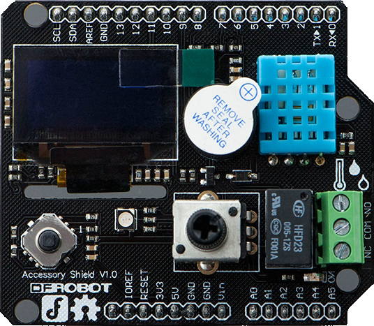
The Bluno Accessory Shield (Manufacturer Part ID: DFR0270) is a versatile expansion board designed by DFRobot to enhance the functionality of Bluno boards. It provides additional connectivity options and interfaces for sensors, actuators, and other peripherals, making it an ideal choice for rapid prototyping and IoT applications. With its user-friendly design, the Bluno Accessory Shield simplifies the integration of hardware components into various projects.
Explore Projects Built with Bluno Accessory Shield
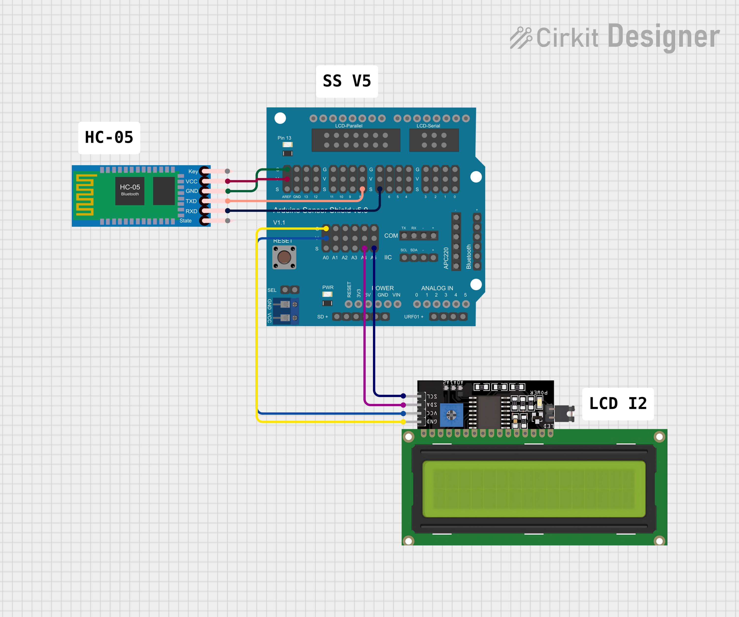
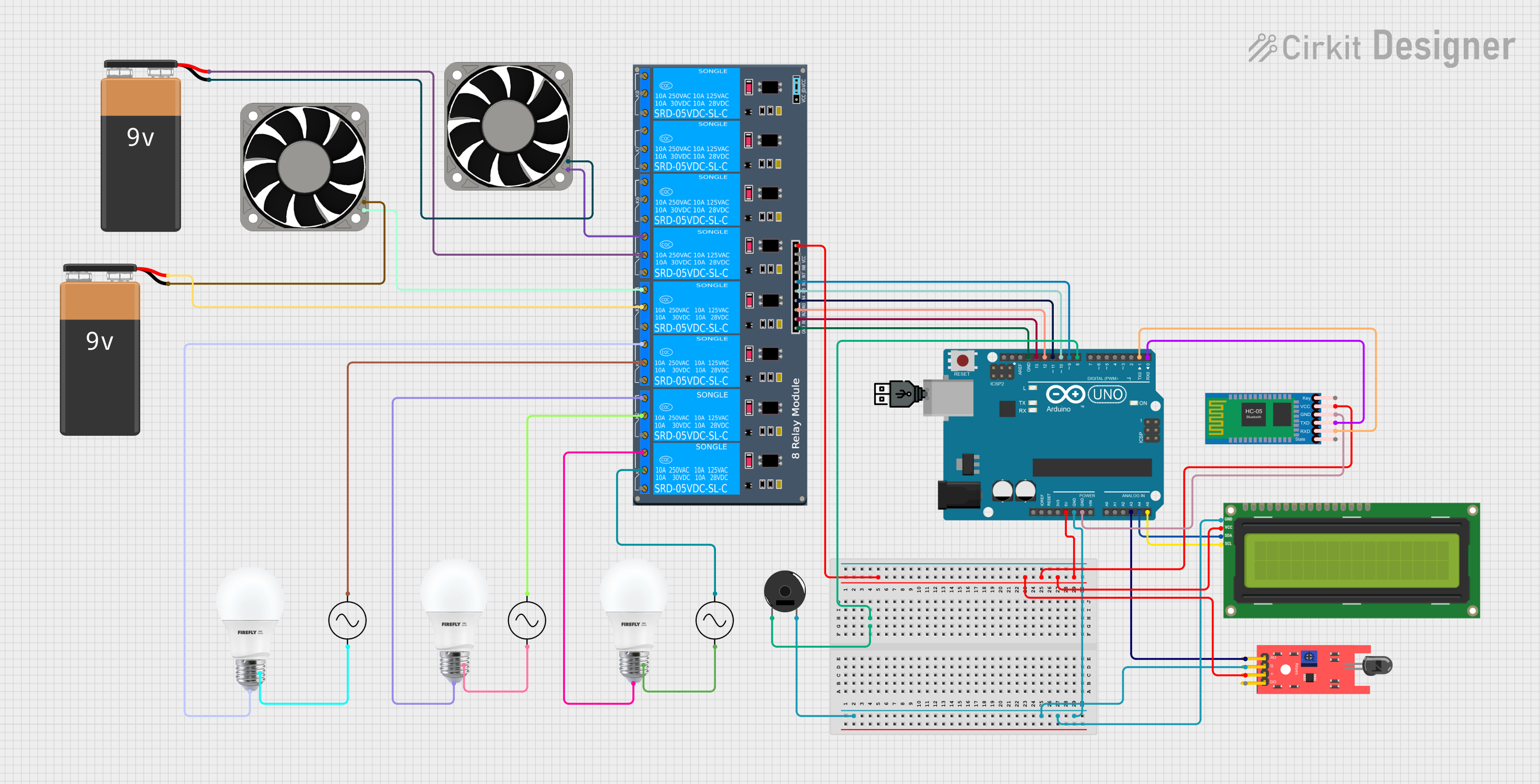
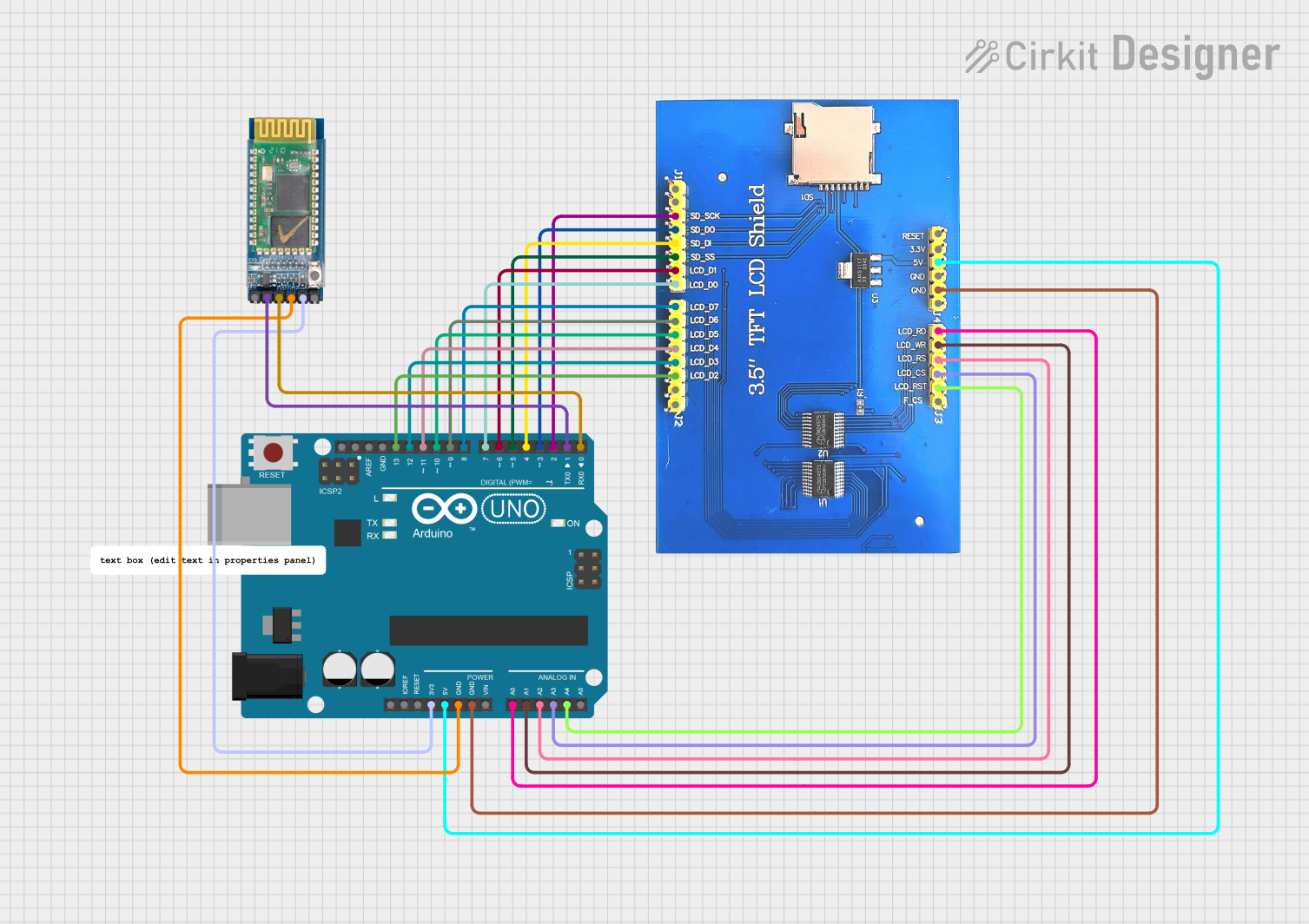
Explore Projects Built with Bluno Accessory Shield
Common Applications and Use Cases
- IoT (Internet of Things) projects requiring multiple sensor connections
- Robotics and automation systems
- Prototyping with Bluno boards for Bluetooth-enabled applications
- Educational projects and workshops
- Smart home devices and environmental monitoring systems
Technical Specifications
The Bluno Accessory Shield is designed to seamlessly integrate with Bluno boards, offering a range of features and interfaces to expand their capabilities.
Key Technical Details
- Input Voltage: 5V (via Bluno board)
- Communication Interfaces: UART, I2C, SPI
- Digital I/O Pins: 14 (compatible with Arduino pinout)
- Analog Input Pins: 6
- Power Output: 5V and 3.3V regulated outputs
- Dimensions: 68.6mm x 53.4mm (standard Arduino shield size)
- Weight: ~30g
- Operating Temperature: -40°C to 85°C
Pin Configuration and Descriptions
The Bluno Accessory Shield follows the standard Arduino pinout, with additional features for enhanced connectivity. Below is a detailed description of the pin configuration:
| Pin | Type | Description |
|---|---|---|
| D0-D13 | Digital I/O | General-purpose digital input/output pins. Supports PWM on specific pins. |
| A0-A5 | Analog Input | Analog input pins for connecting sensors. |
| SDA | I2C Data | Data line for I2C communication. |
| SCL | I2C Clock | Clock line for I2C communication. |
| TX | UART Transmit | Transmit pin for serial communication. |
| RX | UART Receive | Receive pin for serial communication. |
| 5V | Power Output | 5V regulated power output for external components. |
| 3.3V | Power Output | 3.3V regulated power output for external components. |
| GND | Ground | Common ground connection. |
| VIN | Power Input | External power input (if not powered via USB or Bluno board). |
Usage Instructions
The Bluno Accessory Shield is designed for plug-and-play compatibility with Bluno boards. Follow the steps below to use the shield effectively in your projects.
How to Use the Component in a Circuit
- Attach the Shield: Align the pins of the Bluno Accessory Shield with the headers on the Bluno board and press gently to secure the connection.
- Connect Peripherals: Use the digital, analog, or communication pins to connect sensors, actuators, or other peripherals.
- Power the System: Power the Bluno board via USB or an external power source. The shield will draw power from the Bluno board.
- Program the Bluno Board: Write and upload your Arduino-compatible code to the Bluno board using the Arduino IDE.
Important Considerations and Best Practices
- Voltage Compatibility: Ensure that connected peripherals are compatible with the 5V or 3.3V power outputs provided by the shield.
- Pin Conflicts: Avoid using the same pins for multiple peripherals to prevent conflicts.
- Secure Connections: Use jumper wires or connectors to ensure secure and reliable connections to the shield.
- I2C Addressing: When using I2C devices, ensure that each device has a unique address to avoid communication issues.
Example Code for Arduino UNO
The following example demonstrates how to read an analog sensor connected to pin A0 and send the data via serial communication.
// Example: Reading an analog sensor and sending data via serial communication

void setup() {
  Serial.begin(9600); // Initialize serial communication at 9600 baud
  pinMode(A0, INPUT); // Set A0 as an input pin for the analog sensor
}

void loop() {
  int sensorValue = analogRead(A0); // Read the analog value from pin A0
  Serial.print("Sensor Value: ");   // Print a label for the sensor value
  Serial.println(sensorValue);      // Print the sensor value to the serial monitor
  delay(500);                       // Wait for 500ms before the next reading
}
Troubleshooting and FAQs
Common Issues Users Might Face
Shield Not Detected by Bluno Board:
- Cause: Improper connection between the shield and the Bluno board.
- Solution: Ensure the shield is firmly attached to the Bluno board with all pins aligned correctly.
Peripheral Not Responding:
- Cause: Incorrect wiring or pin configuration.
- Solution: Double-check the wiring and ensure the correct pins are used in the code.
I2C Communication Failure:
- Cause: Address conflict between I2C devices.
- Solution: Verify that each I2C device has a unique address and update the code accordingly.
Power Issues:
- Cause: Excessive current draw from connected peripherals.
- Solution: Ensure the total current draw does not exceed the shield's power output capacity.
Solutions and Tips for Troubleshooting
- Use a multimeter to check voltage levels and continuity in the circuit.
- Test each peripheral individually to isolate issues.
- Refer to the Bluno board and shield datasheets for additional technical details.
By following this documentation, users can effectively utilize the Bluno Accessory Shield in their projects, unlocking its full potential for a wide range of applications.