
How to Use A01NYUB V2: Examples, Pinouts, and Specs
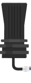
 Design with A01NYUB V2 in Cirkit Designer
A01NYUB V2 Microcontroller Board Documentation
1. Introduction
The A01NYUB V2 is a versatile microcontroller board designed for a wide range of applications, particularly in the fields of IoT (Internet of Things), automation, and rapid prototyping. It features multiple input/output pins, built-in Wi-Fi connectivity, and compatibility with various programming environments, including Arduino IDE, MicroPython, and PlatformIO. Its compact design and robust functionality make it an excellent choice for both beginners and experienced developers.
Common Applications
- IoT devices and smart home systems
- Environmental monitoring and data logging
- Robotics and automation
- Wearable technology
- Prototyping and educational projects
2. Technical Specifications
The following table outlines the key technical details of the A01NYUB V2 microcontroller board:
Key Specifications
| Parameter | Value |
|---|---|
| Microcontroller | ESP32-based dual-core processor |
| Clock Speed | 240 MHz |
| Flash Memory | 4 MB |
| SRAM | 520 KB |
| Wi-Fi Connectivity | IEEE 802.11 b/g/n (2.4 GHz) |
| Operating Voltage | 3.3V |
| Input Voltage Range | 5V (via USB) or 7-12V (via VIN pin) |
| GPIO Pins | 30 (including digital, analog, PWM, and I2C/SPI/UART support) |
| ADC Channels | 18 (12-bit resolution) |
| PWM Channels | 16 |
| Communication Protocols | UART, SPI, I2C, I2S, CAN |
| USB Interface | Micro-USB (for programming and power) |
| Dimensions | 58 mm x 25 mm |
| Operating Temperature | -40°C to +85°C |
Pin Configuration
The A01NYUB V2 features a total of 30 GPIO pins, each with specific functions. Below is a summary of the pin configuration:
| Pin | Function | Description |
|---|---|---|
| VIN | Power Input | Accepts 7-12V input for powering the board. |
| GND | Ground | Common ground for the circuit. |
| 3V3 | 3.3V Output | Provides 3.3V output for external components. |
| GPIO0 | Digital I/O, ADC, PWM | General-purpose pin with ADC and PWM support. |
| GPIO1 | UART TX | Transmit pin for UART communication. |
| GPIO2 | Digital I/O, ADC, PWM | General-purpose pin with ADC and PWM support. |
| GPIO3 | UART RX | Receive pin for UART communication. |
| GPIO4 | Digital I/O, ADC, PWM | General-purpose pin with ADC and PWM support. |
| GPIO5 | Digital I/O, ADC, PWM | General-purpose pin with ADC and PWM support. |
| GPIO12 | Digital I/O, ADC, PWM | General-purpose pin with ADC and PWM support. |
| GPIO13 | Digital I/O, ADC, PWM | General-purpose pin with ADC and PWM support. |
| GPIO14 | Digital I/O, ADC, PWM | General-purpose pin with ADC and PWM support. |
| GPIO15 | Digital I/O, ADC, PWM | General-purpose pin with ADC and PWM support. |
| GPIO16 | Digital I/O | General-purpose pin. |
| GPIO17 | Digital I/O | General-purpose pin. |
| GPIO18 | SPI SCK | Serial Clock for SPI communication. |
| GPIO19 | SPI MISO | Master In Slave Out for SPI communication. |
| GPIO21 | I2C SDA | Data line for I2C communication. |
| GPIO22 | I2C SCL | Clock line for I2C communication. |
| GPIO23 | SPI MOSI | Master Out Slave In for SPI communication. |
3. Usage Instructions
Getting Started
Powering the Board:
- Connect the board to your computer using a Micro-USB cable for power and programming.
- Alternatively, supply 7-12V to the VIN pin for standalone operation.
Programming the Board:
- Install the Arduino IDE or any compatible programming environment.
- Add the ESP32 board support package to your IDE.
- Select "A01NYUB V2" or a compatible ESP32 board from the board manager.
- Connect the board to your computer and upload your code.
Connecting Peripherals:
- Use the GPIO pins to connect sensors, actuators, or other peripherals.
- Ensure that the voltage and current requirements of your peripherals are compatible with the board.
Example Circuit
Below is an example of connecting an LED to GPIO2:
- Connect the positive leg of the LED to GPIO2 through a 220-ohm resistor.
- Connect the negative leg of the LED to GND.
Example Code
The following code demonstrates how to blink an LED connected to GPIO2:
// Define the GPIO pin where the LED is connected
#define LED_PIN 2

void setup() {
  // Set the LED pin as an output
  pinMode(LED_PIN, OUTPUT);
}

void loop() {
  // Turn the LED on
  digitalWrite(LED_PIN, HIGH);
  delay(1000); // Wait for 1 second

  // Turn the LED off
  digitalWrite(LED_PIN, LOW);
  delay(1000); // Wait for 1 second
}
Important Considerations
- Avoid exceeding the maximum voltage and current ratings of the board.
- Use level shifters when interfacing with 5V logic devices.
- Ensure proper grounding to avoid noise and instability in your circuit.
4. Troubleshooting and FAQs
Common Issues and Solutions
| Issue | Possible Cause | Solution |
|---|---|---|
| Board not detected in the IDE | Missing drivers or incorrect board settings | Install the required USB drivers and select the correct board in the IDE. |
| Code upload fails | Incorrect COM port or board not in boot mode | Check the COM port and press the "BOOT" button while uploading the code. |
| Wi-Fi not connecting | Incorrect SSID or password | Verify the Wi-Fi credentials in your code. |
| Peripherals not working as expected | Incorrect pin connections | Double-check the wiring and ensure the correct pins are used in the code. |
FAQs
Can I power the board with a battery?
Yes, you can use a 7-12V battery connected to the VIN pin.What is the maximum current output of the 3.3V pin?
The 3.3V pin can supply up to 500mA, depending on the input power source.Is the board compatible with MicroPython?
Yes, the A01NYUB V2 supports MicroPython, which can be flashed using tools like esptool.How do I reset the board?
Press the "RESET" button on the board to restart it.
This documentation provides a comprehensive guide to using the A01NYUB V2 microcontroller board. Whether you're building an IoT project or experimenting with new ideas, this board offers the flexibility and performance you need.
Explore Projects Built with A01NYUB V2
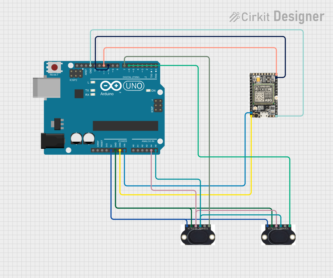
 Open Project in Cirkit Designer
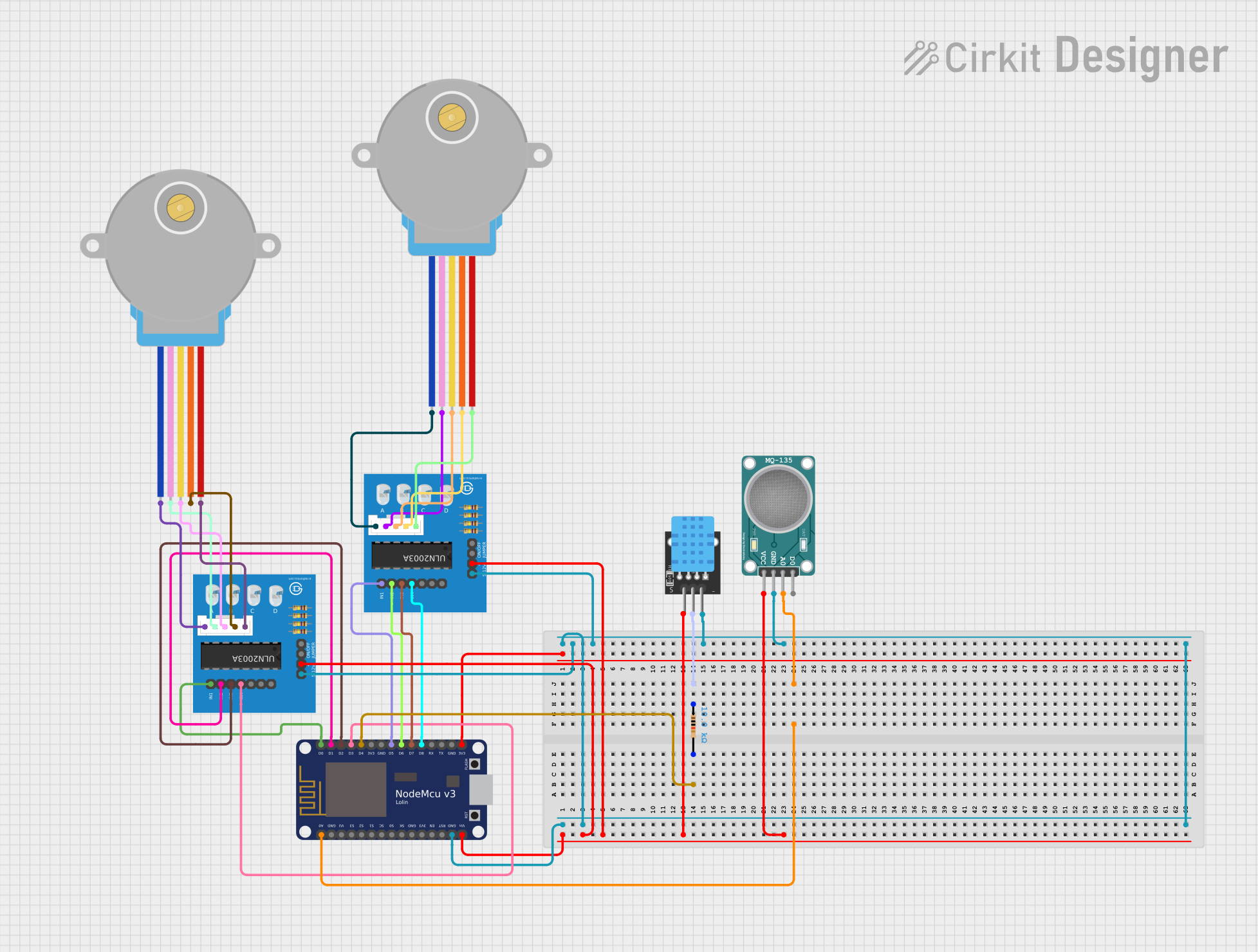
 Open Project in Cirkit Designer
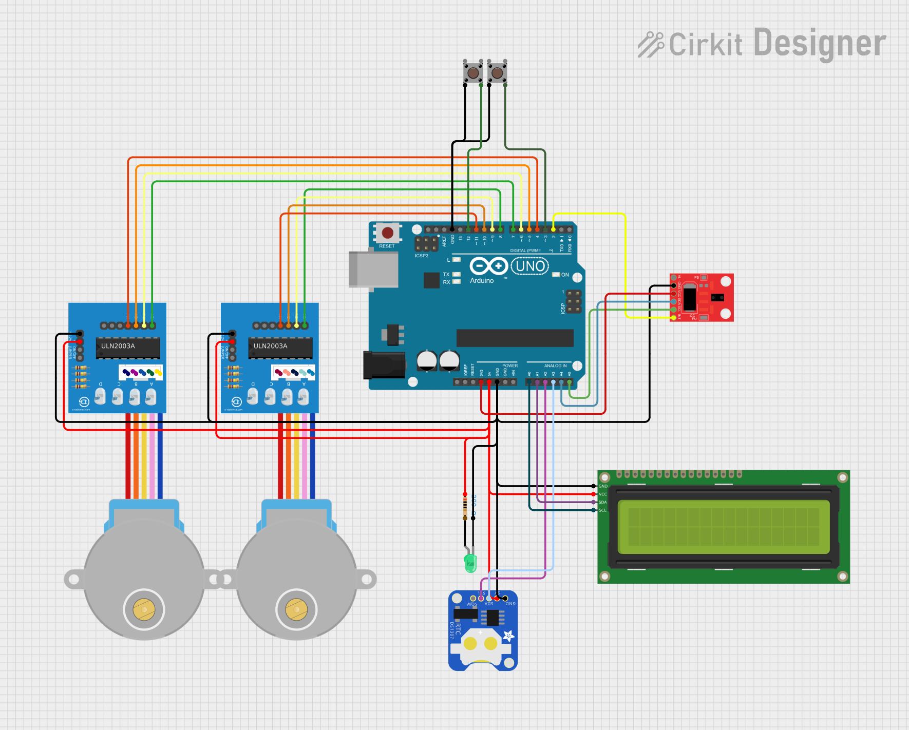
 Open Project in Cirkit Designer
 Open Project in Cirkit Designer
Explore Projects Built with A01NYUB V2

 Open Project in Cirkit Designer
 Open Project in Cirkit Designer
 Open Project in Cirkit Designer
 Open Project in Cirkit Designer