How to Use pwm pulse generator: Examples, Pinouts, and Specs
Introduction
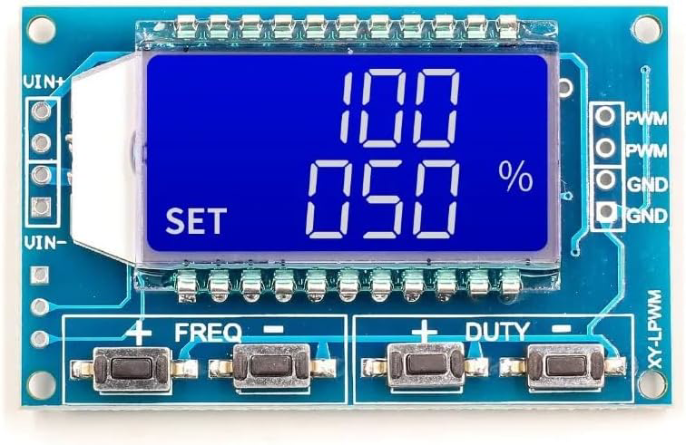
The Holtek PWM (Pulse Width Modulation) Pulse Generator is an electronic component designed to produce square wave signals with adjustable duty cycles. By varying the duty cycle, this component enables precise control of power delivery to connected devices. PWM pulse generators are widely used in applications such as motor speed control, LED brightness adjustment, and signal modulation.
Explore Projects Built with pwm pulse generator


Explore Projects Built with pwm pulse generator
Common Applications and Use Cases
- Motor Control: Adjusting the speed of DC motors by varying the duty cycle.
- LED Dimming: Controlling the brightness of LEDs in lighting systems.
- Signal Modulation: Generating modulated signals for communication systems.
- Power Regulation: Managing power delivery in power supply circuits.
- Audio Applications: Producing audio tones or controlling audio amplifiers.
Technical Specifications
The Holtek PWM Pulse Generator is designed for flexibility and ease of use. Below are its key technical specifications:
| Parameter | Value |
|---|---|
| Supply Voltage (Vcc) | 3.3V to 5V |
| Output Voltage | 0V to Vcc |
| Frequency Range | 1 Hz to 100 kHz |
| Duty Cycle Range | 0% to 100% |
| Output Current | Up to 20 mA |
| Operating Temperature | -40°C to +85°C |
| Package Type | DIP/SOP |
Pin Configuration and Descriptions
The Holtek PWM Pulse Generator typically comes with a 6-pin configuration. Below is the pinout description:
| Pin Number | Pin Name | Description |
|---|---|---|
| 1 | Vcc | Power supply input (3.3V to 5V). |
| 2 | GND | Ground connection. |
| 3 | PWM_OUT | PWM signal output. |
| 4 | FREQ_ADJ | Frequency adjustment pin (connect to a potentiometer). |
| 5 | DUTY_ADJ | Duty cycle adjustment pin (connect to a potentiometer). |
| 6 | ENABLE | Enable/disable the PWM output (active HIGH). |
Usage Instructions
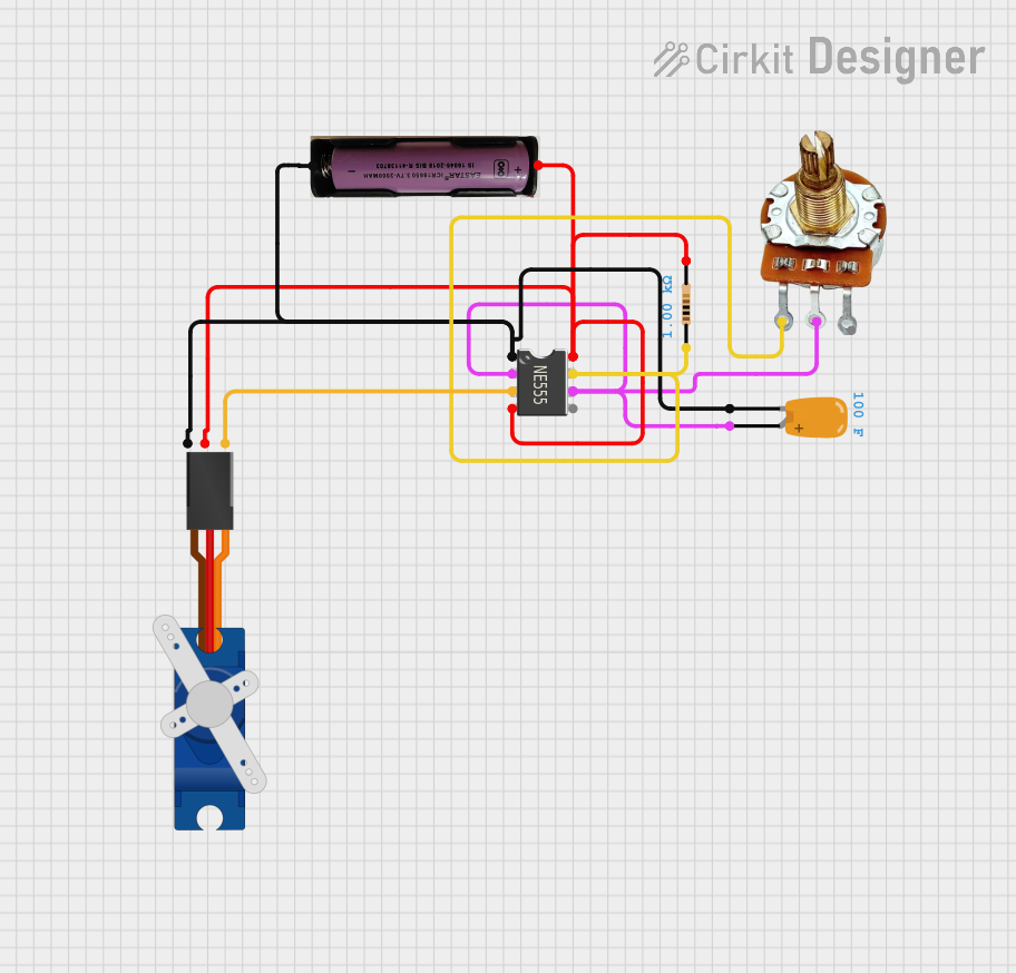
How to Use the Component in a Circuit
- Power Supply: Connect the Vcc pin to a 3.3V or 5V power source and the GND pin to the ground.
- Frequency Adjustment: Connect a potentiometer to the FREQ_ADJ pin to set the desired frequency. Turning the potentiometer will vary the frequency of the PWM signal.
- Duty Cycle Adjustment: Connect another potentiometer to the DUTY_ADJ pin to control the duty cycle. Adjusting this potentiometer will change the width of the pulses.
- Output Connection: Connect the PWM_OUT pin to the load (e.g., motor, LED, or other devices) to deliver the PWM signal.
- Enable Control: Use the ENABLE pin to turn the PWM output on or off. Pull the pin HIGH to enable the output or LOW to disable it.
Important Considerations and Best Practices
- Decoupling Capacitors: Place a 0.1 µF ceramic capacitor close to the Vcc and GND pins to reduce noise and stabilize the power supply.
- Load Protection: If driving high-current loads, use a transistor or MOSFET as a buffer to protect the PWM generator.
- Frequency and Duty Cycle Adjustment: Use high-quality potentiometers for precise control of frequency and duty cycle.
- Heat Management: Ensure proper ventilation or heat dissipation if the component operates at high frequencies or drives heavy loads.
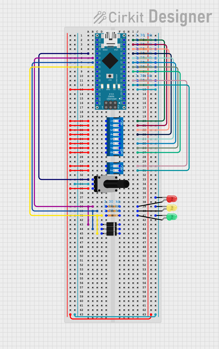
Example: Using the PWM Pulse Generator with an Arduino UNO
The Holtek PWM Pulse Generator can be used alongside an Arduino UNO for additional control. Below is an example Arduino sketch to control the ENABLE pin:
// Example: Controlling the ENABLE pin of the Holtek PWM Pulse Generator
// Connect the ENABLE pin of the PWM generator to Arduino pin 7

const int enablePin = 7; // Define the Arduino pin connected to ENABLE

void setup() {
  pinMode(enablePin, OUTPUT); // Set the ENABLE pin as an output
  digitalWrite(enablePin, LOW); // Start with the PWM output disabled
}

void loop() {
  // Enable the PWM output for 5 seconds
  digitalWrite(enablePin, HIGH);
  delay(5000); // Wait for 5 seconds

  // Disable the PWM output for 5 seconds
  digitalWrite(enablePin, LOW);
  delay(5000); // Wait for 5 seconds
}
Troubleshooting and FAQs
Common Issues and Solutions
No Output Signal:
- Cause: The ENABLE pin is not set HIGH.
- Solution: Ensure the ENABLE pin is connected to a HIGH signal or directly to Vcc.
Unstable Frequency or Duty Cycle:
- Cause: Poor-quality potentiometers or loose connections.
- Solution: Use high-quality potentiometers and check all connections.
Overheating:
- Cause: Driving a high-current load directly from the PWM_OUT pin.
- Solution: Use a transistor or MOSFET to handle high-current loads.
Noise in the Output Signal:
- Cause: Insufficient decoupling or noisy power supply.
- Solution: Add a 0.1 µF ceramic capacitor near the Vcc and GND pins.
FAQs
Q1: Can I use the PWM pulse generator with a 12V power supply?
A1: No, the PWM pulse generator is designed to operate with a supply voltage of 3.3V to 5V. Using a higher voltage may damage the component.
Q2: How do I achieve a 50% duty cycle?
A2: Adjust the potentiometer connected to the DUTY_ADJ pin until the output signal has equal ON and OFF times.
Q3: Can I control the frequency and duty cycle programmatically?
A3: Yes, you can replace the potentiometers with digital-to-analog converters (DACs) or use a microcontroller with PWM outputs to control the FREQ_ADJ and DUTY_ADJ pins.
Q4: What is the maximum load current the PWM_OUT pin can handle?
A4: The PWM_OUT pin can handle up to 20 mA. For higher currents, use an external transistor or MOSFET.
This concludes the documentation for the Holtek PWM Pulse Generator.