Cirkit Designer Logo
Cirkit Designer
Your all-in-one circuit design IDE
Home / 
Component Documentation

How to Use OpenSegment Serial Display - 20mm (Yellow): Examples, Pinouts, and Specs

Image of OpenSegment Serial Display - 20mm (Yellow)
Cirkit Designer LogoDesign with OpenSegment Serial Display - 20mm (Yellow) in Cirkit Designer

Introduction

The OpenSegment Serial Display is a 20mm alphanumeric LED module that features four 7-segment displays with a bright yellow color. This display is designed for readability and ease of use, making it an excellent choice for projects requiring numerical output that is both compact and visually appealing. Common applications include clocks, counters, timers, and any project where numerical data needs to be presented to a user.

Explore Projects Built with OpenSegment Serial Display - 20mm (Yellow)

Use Cirkit Designer to design, explore, and prototype these projects online. Some projects support real-time simulation. Click "Open Project" to start designing instantly!
ESP32-Powered OLED Display Interface
Image of Display: A project utilizing OpenSegment Serial Display - 20mm (Yellow) in a practical application
This circuit connects an ESP32 microcontroller to a 0.96" OLED display via I2C communication protocol. The ESP32's pins D22 and D21 are used as the serial clock (SCK) and serial data (SDA) lines, respectively, to interface with the OLED's corresponding SCK and SDA pins. The OLED is powered by the 3.3V output from the ESP32, and both devices share a common ground. The embedded code initializes the display and prints 'Hello, ESP32!' on the screen.
Cirkit Designer LogoOpen Project in Cirkit Designer
Arduino UNO Controlled TCS3200 Color Sensor with I2C LCD Display
Image of CeledonioT3: A project utilizing OpenSegment Serial Display - 20mm (Yellow) in a practical application
This circuit features an Arduino UNO microcontroller interfaced with a TCS3200 color sensor and an I2C LCD 16x2 display. The TCS3200 color sensor's output is connected to the Arduino's digital pin D12, and its frequency scaling pins (S0-S3) are connected to digital pins D8-D11 for configuration. The LCD display communicates with the Arduino via the I2C protocol, using A4 (SDA) and A5 (SCL) for data transfer, allowing the system to display color readings or other information from the sensor.
Cirkit Designer LogoOpen Project in Cirkit Designer
Arduino UNO Controlled Seven-Segment Display Counter
Image of Arduino Uno - Seven Segment Display (Sim-C): A project utilizing OpenSegment Serial Display - 20mm (Yellow) in a practical application
This circuit uses an Arduino UNO to control a seven-segment display, displaying digits from 0 to 9 with a one-second delay between each digit. The Arduino drives the segments of the common anode display by setting the corresponding pins to LOW, as defined in the provided sketch code.
Cirkit Designer LogoOpen Project in Cirkit Designer
Arduino UNO Based Ultrasonic Distance Measurement with TM1637 Display
Image of UNDERWATER SENSOR: A project utilizing OpenSegment Serial Display - 20mm (Yellow) in a practical application
This circuit is designed to measure distance using the JSN-SR04T ultrasonic sensor and display the measured value on a TM1637 4-digit 7-segment display. The Arduino UNO serves as the central controller, running code to operate the sensor, calculate the distance, and update the display. The sensor's TRIG and ECHO pins are connected to digital pins D12 and D11 of the Arduino, respectively, while the display's CLK and DIO pins are connected to digital pins D3 and D4, with both the sensor and display sharing power and ground connections with the Arduino.
Cirkit Designer LogoOpen Project in Cirkit Designer

Explore Projects Built with OpenSegment Serial Display - 20mm (Yellow)

Use Cirkit Designer to design, explore, and prototype these projects online. Some projects support real-time simulation. Click "Open Project" to start designing instantly!
Image of Display: A project utilizing OpenSegment Serial Display - 20mm (Yellow) in a practical application
ESP32-Powered OLED Display Interface
This circuit connects an ESP32 microcontroller to a 0.96" OLED display via I2C communication protocol. The ESP32's pins D22 and D21 are used as the serial clock (SCK) and serial data (SDA) lines, respectively, to interface with the OLED's corresponding SCK and SDA pins. The OLED is powered by the 3.3V output from the ESP32, and both devices share a common ground. The embedded code initializes the display and prints 'Hello, ESP32!' on the screen.
Cirkit Designer LogoOpen Project in Cirkit Designer
Image of CeledonioT3: A project utilizing OpenSegment Serial Display - 20mm (Yellow) in a practical application
Arduino UNO Controlled TCS3200 Color Sensor with I2C LCD Display
This circuit features an Arduino UNO microcontroller interfaced with a TCS3200 color sensor and an I2C LCD 16x2 display. The TCS3200 color sensor's output is connected to the Arduino's digital pin D12, and its frequency scaling pins (S0-S3) are connected to digital pins D8-D11 for configuration. The LCD display communicates with the Arduino via the I2C protocol, using A4 (SDA) and A5 (SCL) for data transfer, allowing the system to display color readings or other information from the sensor.
Cirkit Designer LogoOpen Project in Cirkit Designer
Image of Arduino Uno - Seven Segment Display (Sim-C): A project utilizing OpenSegment Serial Display - 20mm (Yellow) in a practical application
Arduino UNO Controlled Seven-Segment Display Counter
This circuit uses an Arduino UNO to control a seven-segment display, displaying digits from 0 to 9 with a one-second delay between each digit. The Arduino drives the segments of the common anode display by setting the corresponding pins to LOW, as defined in the provided sketch code.
Cirkit Designer LogoOpen Project in Cirkit Designer
Image of UNDERWATER SENSOR: A project utilizing OpenSegment Serial Display - 20mm (Yellow) in a practical application
Arduino UNO Based Ultrasonic Distance Measurement with TM1637 Display
This circuit is designed to measure distance using the JSN-SR04T ultrasonic sensor and display the measured value on a TM1637 4-digit 7-segment display. The Arduino UNO serves as the central controller, running code to operate the sensor, calculate the distance, and update the display. The sensor's TRIG and ECHO pins are connected to digital pins D12 and D11 of the Arduino, respectively, while the display's CLK and DIO pins are connected to digital pins D3 and D4, with both the sensor and display sharing power and ground connections with the Arduino.
Cirkit Designer LogoOpen Project in Cirkit Designer

Technical Specifications

Key Technical Details

  • Display Color: Yellow
  • Number of Digits: 4
  • Digit Height: 20mm
  • Operating Voltage: 3.3V to 7V
  • Maximum Current: 80mA (typical usage)
  • Communication Interface: Serial (TTL)
  • Baud Rate: 9600 to 115200 (default 9600)
  • Operating Temperature Range: -40°C to 85°C

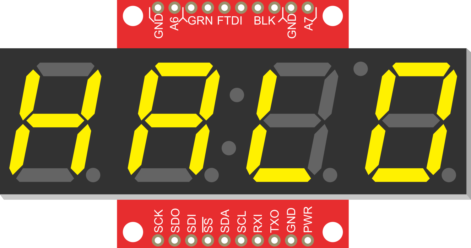
Pin Configuration and Descriptions

Pin Number Name Description
1 VCC Power supply (3.3V to 7V)
2 GND Ground connection
3 RX Serial Receive Pin
4 TX Serial Transmit Pin (not used)

Usage Instructions

Connecting to a Circuit

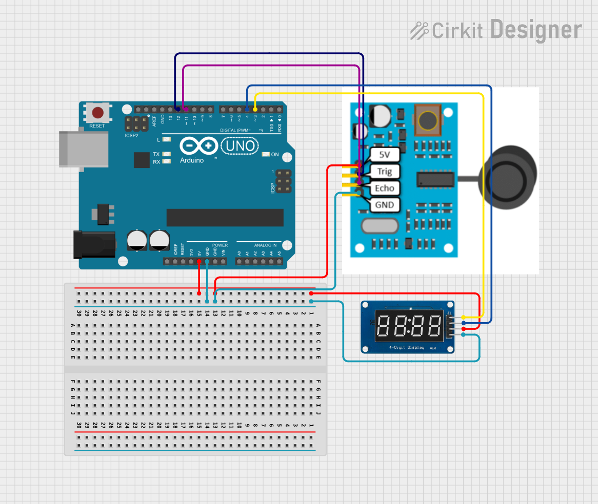
To use the OpenSegment Serial Display with a microcontroller like an Arduino UNO, follow these steps:

  1. Connect the VCC pin to the 5V output on the Arduino.
  2. Connect the GND pin to one of the GND pins on the Arduino.
  3. Connect the RX pin on the display to a TX pin on the Arduino (e.g., Digital Pin 1).

Programming the Display

Here is an example code snippet for controlling the OpenSegment Serial Display with an Arduino UNO:

#include <SoftwareSerial.h>

// Create a software serial port on pins 10 (RX) and 11 (TX)
SoftwareSerial openSegmentSerial(10, 11);

void setup() {
  // Set the data rate for the SoftwareSerial port
  openSegmentSerial.begin(9600);
}

void loop() {
  // Send a number to the display
  openSegmentSerial.print("1234");
  delay(1000); // Wait for a second

  // Clear the display
  openSegmentSerial.write(0x76); // Clear command for OpenSegment
  delay(1000); // Wait for a second
}

Important Considerations and Best Practices

  • Ensure that the power supply voltage does not exceed the maximum rating of 7V.
  • When sending serial data, adhere to the baud rate configured on the display.
  • Avoid looking directly at the LEDs for extended periods, as the brightness can be intense.

Troubleshooting and FAQs

Common Issues

  • Display Not Lighting Up: Check the power connections and ensure that the voltage is within the specified range.
  • Garbled or No Output: Verify that the baud rate of the microcontroller matches the display's baud rate.
  • Partial Display: Ensure that all data pins are properly connected and that there are no soldering issues.

Solutions and Tips for Troubleshooting

  • Double-check all connections, especially the VCC and GND pins.
  • Use a multimeter to verify that the correct voltage is reaching the display.
  • If using a new baud rate, remember to configure the display to match it.
  • For any persistent issues, consult the manufacturer's datasheet and support forums.

FAQs

Q: Can I chain multiple displays together? A: Yes, multiple OpenSegment displays can be daisy-chained using the RX and TX pins.

Q: How do I change the baud rate? A: The baud rate can be changed using serial commands. Refer to the manufacturer's documentation for the specific command sequence.

Q: Is it possible to display letters as well as numbers? A: The OpenSegment display can show a limited set of letters that are common to 7-segment displays.

Q: Can I control the brightness of the display? A: Yes, the brightness can be controlled via serial commands. Check the datasheet for the appropriate command.

Remember to always refer to the manufacturer's datasheet for the most accurate and detailed information regarding the OpenSegment Serial Display.