Cirkit Designer Logo
Cirkit Designer
Your all-in-one circuit design IDE
Home / 
Component Documentation

How to Use ESP32S3 WROOM-1U: Examples, Pinouts, and Specs

Image of ESP32S3 WROOM-1U
Cirkit Designer LogoDesign with ESP32S3 WROOM-1U in Cirkit Designer

Introduction

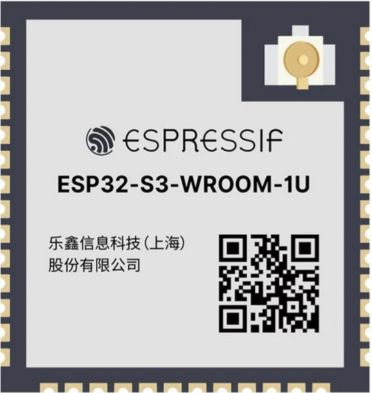
The ESP32-S3-WROOM-1U is a high-performance Wi-Fi and Bluetooth microcontroller module developed by Espressif. It features a dual-core processor, integrated memory, and a wide range of GPIO options, making it an excellent choice for IoT (Internet of Things) applications. This module is designed for applications requiring high processing power, wireless connectivity, and low power consumption.

Explore Projects Built with ESP32S3 WROOM-1U

Use Cirkit Designer to design, explore, and prototype these projects online. Some projects support real-time simulation. Click "Open Project" to start designing instantly!
ESP32-Based GPS Tracker with SD Card Logging and Barometric Sensor
Image of gps projekt circuit: A project utilizing ESP32S3 WROOM-1U in a practical application
This circuit features an ESP32 Wroom Dev Kit as the main microcontroller, interfaced with an MPL3115A2 sensor for pressure and temperature readings, and a Neo 6M GPS module for location tracking. The ESP32 is also connected to an SD card reader for data logging purposes. A voltage regulator is used to step down the USB power supply to 3.3V, which powers the ESP32, the sensor, and the SD card reader.
Cirkit Designer LogoOpen Project in Cirkit Designer
ESP32-Based Multi-Sensor Health Monitoring System with Bluetooth Connectivity
Image of circuit diagram: A project utilizing ESP32S3 WROOM-1U in a practical application
This circuit features an ESP32-WROOM-32UE microcontroller as the central processing unit, interfacing with a variety of sensors and modules. It includes a MAX30100 pulse oximeter and heart-rate sensor, an MLX90614 infrared thermometer, an HC-05 Bluetooth module for wireless communication, and a Neo 6M GPS module for location tracking. All components are powered by a common voltage supply and are connected to specific GPIO pins on the ESP32 for data exchange, with the sensors using I2C communication and the modules using UART.
Cirkit Designer LogoOpen Project in Cirkit Designer
ESP32-Based Vibration Motor Controller with I2C IO Expansion
Image of VIBRATYION: A project utilizing ESP32S3 WROOM-1U in a practical application
This circuit features an ESP32 Wroom Dev Kit microcontroller interfaced with an MCP23017 I/O expansion board via I2C communication, utilizing GPIO 21 and GPIO 22 for SDA and SCL lines, respectively. A vibration motor is controlled by an NPN transistor acting as a switch, with a diode for back EMF protection and a resistor to limit base current. The ESP32 can control the motor by sending signals to the MCP23017, which then interfaces with the transistor to turn the motor on or off.
Cirkit Designer LogoOpen Project in Cirkit Designer
ESP32-S3 Based Vibration Detection System with TFT Display and Power Backup
Image of IOT Thesis: A project utilizing ESP32S3 WROOM-1U in a practical application
This circuit features an ESP32-S3 microcontroller connected to various peripherals including an ADXL355 accelerometer, an SW-420 vibration sensor, a buzzer module, and an ILI9341 TFT display. The ESP32-S3 manages sensor inputs and provides output to the display and buzzer. Power management is handled by a 12V to 5V step-down converter, and a UPS ensures uninterrupted power supply, with a rocker switch to control the power flow.
Cirkit Designer LogoOpen Project in Cirkit Designer

Explore Projects Built with ESP32S3 WROOM-1U

Use Cirkit Designer to design, explore, and prototype these projects online. Some projects support real-time simulation. Click "Open Project" to start designing instantly!
Image of gps projekt circuit: A project utilizing ESP32S3 WROOM-1U in a practical application
ESP32-Based GPS Tracker with SD Card Logging and Barometric Sensor
This circuit features an ESP32 Wroom Dev Kit as the main microcontroller, interfaced with an MPL3115A2 sensor for pressure and temperature readings, and a Neo 6M GPS module for location tracking. The ESP32 is also connected to an SD card reader for data logging purposes. A voltage regulator is used to step down the USB power supply to 3.3V, which powers the ESP32, the sensor, and the SD card reader.
Cirkit Designer LogoOpen Project in Cirkit Designer
Image of circuit diagram: A project utilizing ESP32S3 WROOM-1U in a practical application
ESP32-Based Multi-Sensor Health Monitoring System with Bluetooth Connectivity
This circuit features an ESP32-WROOM-32UE microcontroller as the central processing unit, interfacing with a variety of sensors and modules. It includes a MAX30100 pulse oximeter and heart-rate sensor, an MLX90614 infrared thermometer, an HC-05 Bluetooth module for wireless communication, and a Neo 6M GPS module for location tracking. All components are powered by a common voltage supply and are connected to specific GPIO pins on the ESP32 for data exchange, with the sensors using I2C communication and the modules using UART.
Cirkit Designer LogoOpen Project in Cirkit Designer
Image of VIBRATYION: A project utilizing ESP32S3 WROOM-1U in a practical application
ESP32-Based Vibration Motor Controller with I2C IO Expansion
This circuit features an ESP32 Wroom Dev Kit microcontroller interfaced with an MCP23017 I/O expansion board via I2C communication, utilizing GPIO 21 and GPIO 22 for SDA and SCL lines, respectively. A vibration motor is controlled by an NPN transistor acting as a switch, with a diode for back EMF protection and a resistor to limit base current. The ESP32 can control the motor by sending signals to the MCP23017, which then interfaces with the transistor to turn the motor on or off.
Cirkit Designer LogoOpen Project in Cirkit Designer
Image of IOT Thesis: A project utilizing ESP32S3 WROOM-1U in a practical application
ESP32-S3 Based Vibration Detection System with TFT Display and Power Backup
This circuit features an ESP32-S3 microcontroller connected to various peripherals including an ADXL355 accelerometer, an SW-420 vibration sensor, a buzzer module, and an ILI9341 TFT display. The ESP32-S3 manages sensor inputs and provides output to the display and buzzer. Power management is handled by a 12V to 5V step-down converter, and a UPS ensures uninterrupted power supply, with a rocker switch to control the power flow.
Cirkit Designer LogoOpen Project in Cirkit Designer

Common Applications and Use Cases

  • Smart home devices (e.g., smart lights, thermostats)
  • Wearable electronics
  • Industrial IoT systems
  • Wireless sensor networks
  • Robotics and automation
  • Audio streaming and voice recognition systems

Technical Specifications

The ESP32-S3-WROOM-1U module is built for versatility and performance. Below are its key technical details:

Key Technical Details

Parameter Specification
Microcontroller ESP32-S3 (Xtensa® 32-bit LX7 dual-core processor)
Clock Speed Up to 240 MHz
Wireless Connectivity Wi-Fi 802.11 b/g/n (2.4 GHz), Bluetooth 5 (LE)
Flash Memory 4 MB (default)
SRAM 512 KB
PSRAM (Optional) Up to 8 MB
Operating Voltage 3.0V to 3.6V
GPIO Pins 45 (configurable for various functions)
Interfaces SPI, I2C, I2S, UART, PWM, ADC, DAC, USB-OTG
Power Consumption Ultra-low power in deep sleep mode (~10 µA)
Antenna External antenna (U.FL connector)
Dimensions 13.2 mm x 16.6 mm x 2.4 mm

Pin Configuration and Descriptions

The ESP32-S3-WROOM-1U module has a total of 38 pins exposed for use. Below is the pinout description:

Pin Number Name Function Description
1 GND Ground
2 3V3 Power supply (3.3V)
3 EN Enable pin (active high)
4 IO0 GPIO0, boot mode selection, ADC, or other uses
5 IO1 GPIO1, UART TXD, or other uses
6 IO2 GPIO2, ADC, or other uses
7 IO3 GPIO3, UART RXD, or other uses
8 IO4 GPIO4, PWM, or other uses
... ... ...
38 IO37 GPIO37, ADC, or other uses

Note: Refer to the official datasheet for the complete pinout and advanced configurations.

Usage Instructions

The ESP32-S3-WROOM-1U is versatile and can be used in a variety of circuits. Below are the steps and best practices for using this module:

How to Use the Component in a Circuit

  1. Power Supply: Provide a stable 3.3V power supply to the 3V3 pin. Ensure the current rating of the power source meets the module's requirements.
  2. Boot Mode: Connect the IO0 pin to GND during power-up to enter bootloader mode for programming.
  3. External Antenna: Attach an external antenna to the U.FL connector for optimal wireless performance.
  4. GPIO Configuration: Configure the GPIO pins as needed for your application (e.g., input, output, ADC, PWM).
  5. Programming: Use the USB-OTG interface or an external UART-to-USB converter to upload firmware.

Important Considerations and Best Practices

  • Decoupling Capacitors: Place decoupling capacitors (e.g., 0.1 µF) near the power pins to reduce noise.
  • Antenna Placement: Ensure the external antenna is placed away from metal objects to avoid signal interference.
  • Deep Sleep Mode: Use the deep sleep mode to minimize power consumption in battery-powered applications.
  • Firmware Updates: Always use the latest firmware from Espressif to ensure optimal performance and security.

Example: Connecting to an Arduino UNO

The ESP32-S3-WROOM-1U can be programmed using the Arduino IDE. Below is an example code snippet to connect the module to a Wi-Fi network:

#include <WiFi.h> // Include the Wi-Fi library for ESP32

// Replace with your network credentials
const char* ssid = "Your_SSID";
const char* password = "Your_PASSWORD";

void setup() {
  Serial.begin(115200); // Initialize serial communication
  delay(1000);

  Serial.println("Connecting to Wi-Fi...");
  WiFi.begin(ssid, password); // Start Wi-Fi connection

  while (WiFi.status() != WL_CONNECTED) {
    delay(500);
    Serial.print("."); // Print dots while connecting
  }

  Serial.println("\nWi-Fi connected!");
  Serial.print("IP Address: ");
  Serial.println(WiFi.localIP()); // Print the assigned IP address
}

void loop() {
  // Add your main code here
}

Note: Ensure the ESP32-S3-WROOM-1U is in programming mode when uploading the code.

Troubleshooting and FAQs

Common Issues and Solutions

  1. Module Not Powering On

    • Cause: Insufficient power supply.
    • Solution: Ensure the power source provides a stable 3.3V with sufficient current.
  2. Wi-Fi Connection Fails

    • Cause: Incorrect SSID or password.
    • Solution: Double-check the network credentials in your code.
  3. Cannot Upload Code

    • Cause: Incorrect boot mode or driver issues.
    • Solution: Ensure IO0 is connected to GND during programming and install the correct USB drivers.
  4. Poor Wireless Signal

    • Cause: Antenna placement or interference.
    • Solution: Reposition the antenna and avoid placing it near metal objects.

FAQs

  • Q: Can I use the ESP32-S3-WROOM-1U with a 5V power supply?
    A: No, the module requires a 3.3V power supply. Use a voltage regulator if needed.

  • Q: Does the module support Bluetooth audio?
    A: Yes, the ESP32-S3 supports Bluetooth Low Energy (BLE) and Bluetooth audio applications.

  • Q: How do I reset the module?
    A: Pull the EN pin low momentarily to reset the module.

  • Q: Can I use the module without an external antenna?
    A: No, the ESP32-S3-WROOM-1U requires an external antenna for wireless communication.

By following this documentation, you can effectively integrate the ESP32-S3-WROOM-1U into your projects and troubleshoot common issues. For more advanced configurations, refer to the official Espressif datasheet.