How to Use JST SM Male Connector 3 pin: Examples, Pinouts, and Specs
Introduction
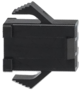
The JST SM Male Connector 3 Pin is a compact and reliable connector designed for secure electrical connections in a variety of electronic applications. Its locking mechanism ensures a stable connection, making it ideal for projects requiring durability and resistance to accidental disconnections. This connector is commonly used in LED lighting systems, robotics, drones, and other low-voltage electronic devices.
Explore Projects Built with JST SM Male Connector 3 pin


Explore Projects Built with JST SM Male Connector 3 pin
Common Applications:
- LED strip connections
- Robotics and automation systems
- RC vehicles and drones
- Power and signal transmission in low-voltage circuits
Technical Specifications
Below are the key technical details and pin configuration for the JST SM Male Connector 3 Pin:
Key Technical Details:
| Parameter | Specification |
|---|---|
| Number of Pins | 3 |
| Connector Type | Male |
| Rated Voltage | 250V AC/DC |
| Rated Current | 3A |
| Wire Gauge Compatibility | 22-28 AWG |
| Material | Nylon (housing), Copper (pins) |
| Operating Temperature | -25°C to +85°C |
| Locking Mechanism | Snap-fit |
Pin Configuration:
| Pin Number | Description | Typical Use Case |
|---|---|---|
| 1 | VCC (Power) | Positive voltage supply |
| 2 | Signal/Data | Data or control signal |
| 3 | GND (Ground) | Ground connection |
Usage Instructions
How to Use the JST SM Male Connector 3 Pin in a Circuit:
- Prepare the Wires: Strip the insulation from the wires you intend to connect, ensuring about 5-7mm of exposed conductor.
- Crimp the Pins: Use a crimping tool to attach the connector pins to the stripped wires. Ensure a secure and firm crimp for reliable connections.
- Insert the Pins: Push the crimped pins into the connector housing until they click into place. Verify that the pins are locked securely.
- Connect to the Female Connector: Align the male connector with the corresponding JST SM Female Connector and push them together until the locking mechanism engages.
- Verify the Connection: Test the connection by gently tugging on the wires to ensure the locking mechanism is secure.
Important Considerations:
- Wire Gauge: Ensure the wires used are within the compatible range (22-28 AWG) for optimal performance.
- Polarity: Double-check the pin configuration to avoid reversing polarity, which could damage connected components.
- Crimping Tool: Use a proper crimping tool designed for JST connectors to achieve a reliable connection.
- Environmental Conditions: Avoid exposing the connector to extreme temperatures or moisture beyond its rated specifications.
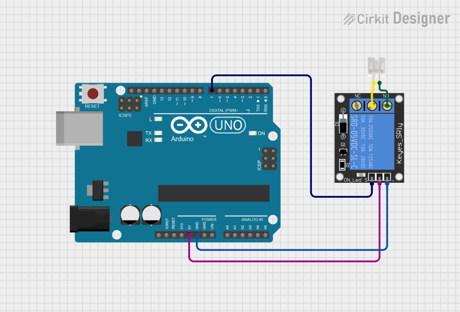
Example: Connecting to an Arduino UNO
The JST SM Male Connector 3 Pin can be used to connect an LED strip to an Arduino UNO. Below is an example of how to wire and program the setup:
Wiring:
- Pin 1 (VCC) connects to the 5V pin on the Arduino.
- Pin 2 (Signal) connects to a PWM-capable digital pin (e.g., D9).
- Pin 3 (GND) connects to the GND pin on the Arduino.
Arduino Code:
// Example code to control an LED strip using a JST SM Male Connector 3 Pin
// connected to an Arduino UNO. The LED strip is connected to pin D9.

const int ledPin = 9; // PWM pin connected to the Signal pin of the connector

void setup() {
  pinMode(ledPin, OUTPUT); // Set the LED pin as an output
}

void loop() {
  analogWrite(ledPin, 128); // Set LED brightness to 50% (128 out of 255)
  delay(1000);              // Wait for 1 second
  analogWrite(ledPin, 0);   // Turn off the LED
  delay(1000);              // Wait for 1 second
}
Troubleshooting and FAQs
Common Issues:
Loose Connection:
- Cause: Pins not fully inserted into the connector housing.
- Solution: Ensure the pins click into place and are securely locked.
Intermittent Signal:
- Cause: Poor crimping of the wires to the pins.
- Solution: Re-crimp the wires using a proper crimping tool.
Reversed Polarity:
- Cause: Incorrect wiring of the VCC and GND pins.
- Solution: Double-check the pin configuration and wiring before powering the circuit.
Connector Does Not Lock:
- Cause: Misalignment of the male and female connectors.
- Solution: Align the connectors properly and ensure the locking mechanism engages.
FAQs:
Q1: Can the JST SM Male Connector 3 Pin handle high-current applications?
A1: No, the connector is rated for a maximum current of 3A. For higher current applications, consider using connectors with higher current ratings.
Q2: Is the connector waterproof?
A2: No, the standard JST SM Male Connector 3 Pin is not waterproof. For outdoor or moisture-prone environments, use waterproof connectors or enclosures.
Q3: Can I reuse the connector pins?
A3: While it is possible to remove and reuse the pins, it is not recommended as it may compromise the reliability of the connection.
Q4: What crimping tool should I use?
A4: Use a crimping tool specifically designed for JST connectors, such as the SN-28B crimping tool, for best results.