How to Use Battery power display 12V with temperature sensor: Examples, Pinouts, and Specs

Introduction
The JS-C35 by Shanghai Jiashen Technology Co., Ltd. is a versatile electronic component designed to monitor the voltage level of a 12V battery while simultaneously measuring and displaying the ambient temperature. This dual-function device ensures that users can keep track of their battery's health and environmental conditions, making it ideal for applications where battery performance and safety are critical.
Explore Projects Built with Battery power display 12V with temperature sensor
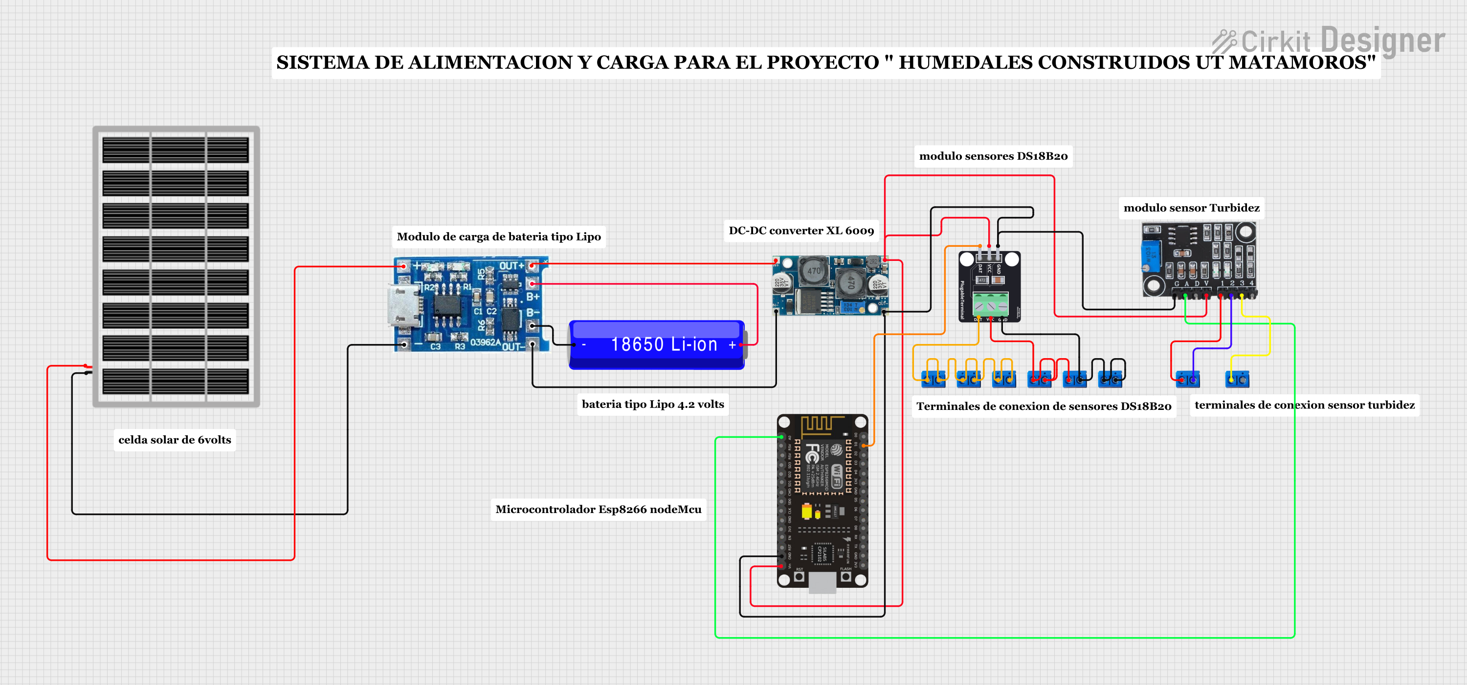
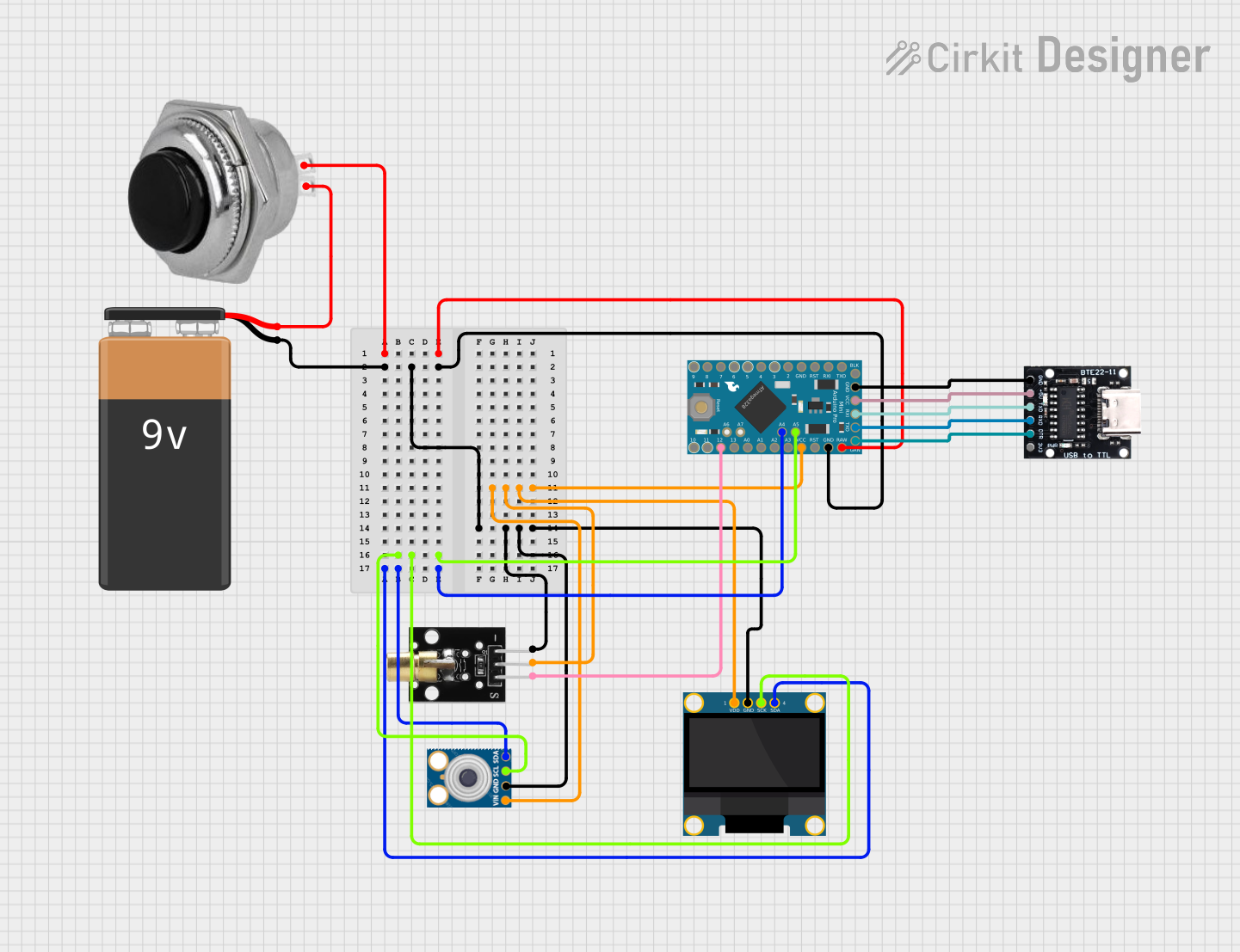
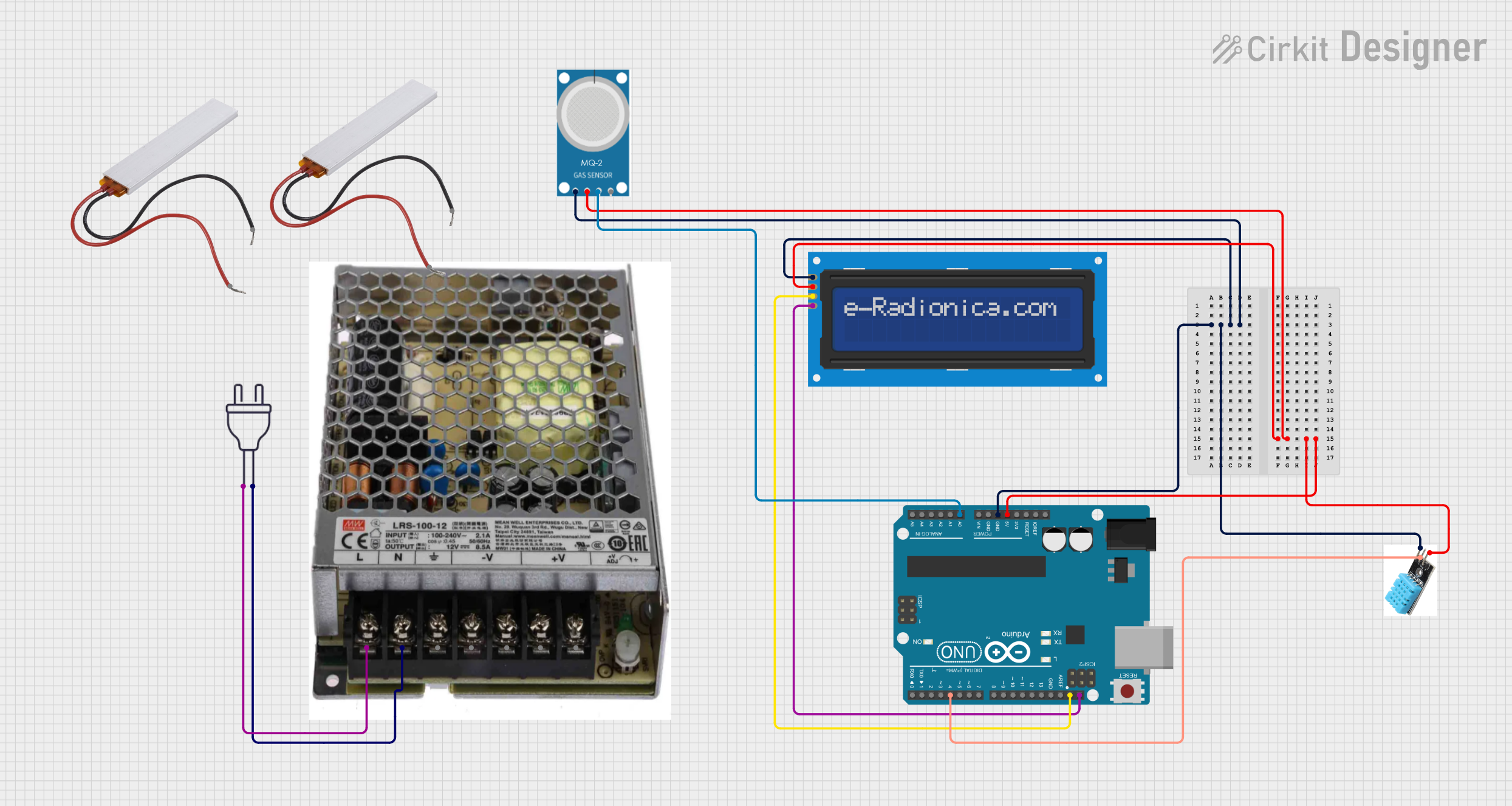
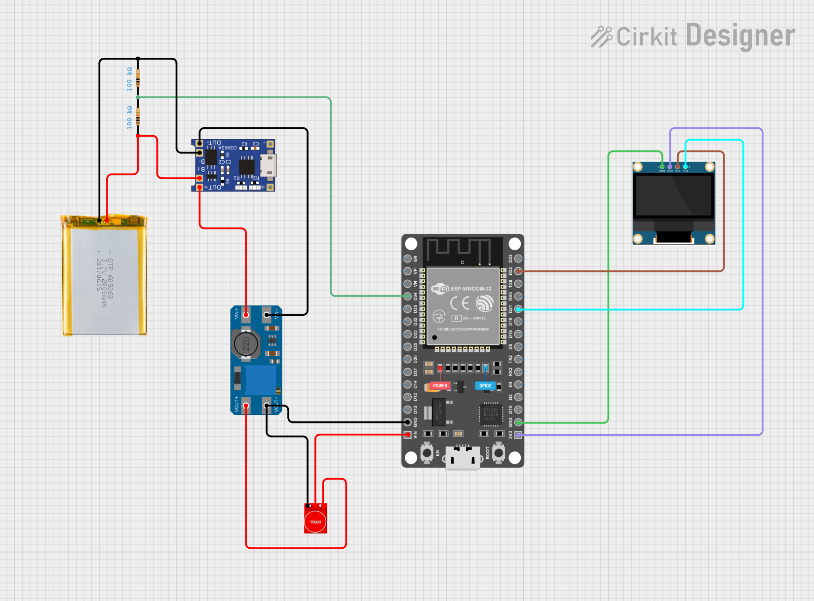
Explore Projects Built with Battery power display 12V with temperature sensor
Common Applications and Use Cases
- Automotive battery monitoring
- Solar power systems
- Uninterruptible Power Supplies (UPS)
- Portable power stations
- DIY electronics projects requiring battery and temperature monitoring
Technical Specifications
The following table outlines the key technical details of the JS-C35:
| Parameter | Value |
|---|---|
| Operating Voltage | 12V DC |
| Voltage Measurement Range | 6V - 15V DC |
| Temperature Range | -20°C to +70°C |
| Display Type | LED (dual display for voltage and temperature) |
| Accuracy (Voltage) | ±0.1V |
| Accuracy (Temperature) | ±1°C |
| Power Consumption | ≤15mA |
| Dimensions | 48mm x 29mm x 21mm |
| Mounting Type | Panel mount |
Pin Configuration and Descriptions
The JS-C35 has a simple wiring interface with three connection points. The table below describes each pin:
| Pin | Label | Description |
|---|---|---|
| 1 | V+ | Positive terminal for 12V DC input |
| 2 | V- | Negative terminal (ground) for 12V DC input |
| 3 | TEMP | Temperature sensor input (pre-wired external sensor) |
Usage Instructions
How to Use the Component in a Circuit
Wiring the Component:
- Connect the V+ pin to the positive terminal of the 12V battery.
- Connect the V- pin to the negative terminal (ground) of the 12V battery.
- Attach the external temperature sensor (pre-wired) to the desired location for temperature measurement.
Mounting:
- The JS-C35 is designed for panel mounting. Use the provided mounting clips or screws to secure the device in place.
Operation:
- Once powered, the LED display will show the battery voltage on one side and the temperature on the other.
- Ensure the temperature sensor is placed in an area free from obstructions for accurate readings.
Important Considerations and Best Practices
- Voltage Range: Ensure the input voltage does not exceed 15V DC to avoid damaging the device.
- Temperature Sensor Placement: Place the sensor away from heat sources or direct sunlight for accurate temperature readings.
- Polarity: Double-check the polarity of the connections before powering the device to prevent short circuits or damage.
- Environmental Conditions: Avoid exposing the device to moisture or extreme temperatures beyond its operating range.
Example: Connecting to an Arduino UNO
The JS-C35 can be used alongside an Arduino UNO for advanced monitoring and control. Below is an example of how to read the voltage and temperature values using the Arduino's analog pins.
Circuit Diagram
- Connect the V+ pin of the JS-C35 to the Arduino's 5V pin.
- Connect the V- pin to the Arduino's GND pin.
- Use an analog pin (e.g., A0) to read the voltage output from the JS-C35.
Arduino Code
// Arduino code to read voltage and temperature from the JS-C35
// Ensure the JS-C35 is properly connected to the Arduino as per the circuit diagram

const int voltagePin = A0; // Analog pin connected to JS-C35 voltage output
const int tempPin = A1;    // Analog pin connected to JS-C35 temperature sensor

void setup() {
  Serial.begin(9600); // Initialize serial communication for debugging
}

void loop() {
  // Read the voltage value from the JS-C35
  int voltageRaw = analogRead(voltagePin);
  float voltage = (voltageRaw / 1023.0) * 5.0 * 3; // Convert to 12V scale

  // Read the temperature value from the JS-C35
  int tempRaw = analogRead(tempPin);
  float temperature = (tempRaw / 1023.0) * 100; // Convert to Celsius (example scaling)

  // Print the results to the Serial Monitor
  Serial.print("Voltage: ");
  Serial.print(voltage);
  Serial.println(" V");

  Serial.print("Temperature: ");
  Serial.print(temperature);
  Serial.println(" °C");

  delay(1000); // Wait 1 second before the next reading
}
Troubleshooting and FAQs
Common Issues and Solutions
| Issue | Possible Cause | Solution |
|---|---|---|
| No display or incorrect readings | Incorrect wiring or reversed polarity | Double-check the wiring and ensure correct polarity. |
| Voltage reading is inaccurate | Input voltage is outside the measurement range | Ensure the input voltage is between 6V and 15V. |
| Temperature reading is inconsistent | Sensor placement is affected by heat sources | Relocate the sensor to a more stable environment. |
| Display flickers or turns off intermittently | Insufficient power supply | Verify that the power source provides a stable 12V DC. |
FAQs
Can the JS-C35 be used with a 24V battery?
- No, the JS-C35 is designed for 12V systems only. Using it with a 24V battery may damage the device.
Is the temperature sensor replaceable?
- The temperature sensor is pre-wired and not designed for replacement. Contact the manufacturer for repair or replacement options.
Can the device be used outdoors?
- The JS-C35 is not waterproof. If outdoor use is required, ensure it is housed in a weatherproof enclosure.
What is the accuracy of the voltage and temperature readings?
- The voltage accuracy is ±0.1V, and the temperature accuracy is ±1°C.
By following this documentation, users can effectively integrate the JS-C35 into their projects and ensure reliable performance.