How to Use AHT10: Examples, Pinouts, and Specs
Introduction
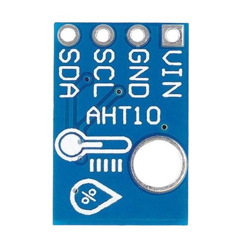
The AHT10 is a high-precision, fully calibrated, digital temperature and humidity sensor. It features a standard I2C interface and is known for its low power consumption and high accuracy. This sensor is ideal for applications requiring precise environmental monitoring, such as HVAC systems, weather stations, and smart home devices.
Explore Projects Built with AHT10
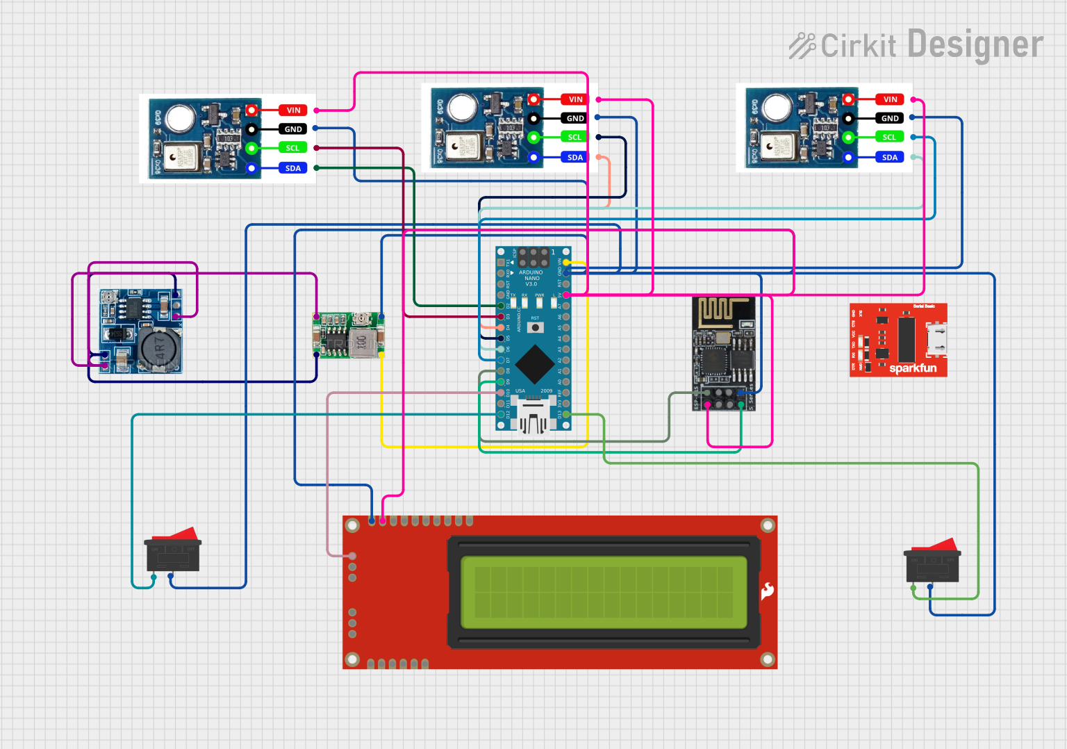
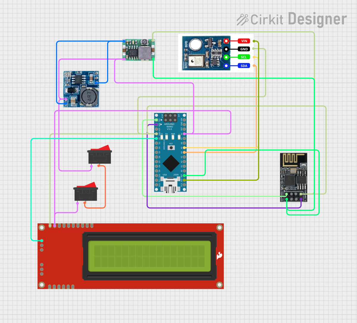
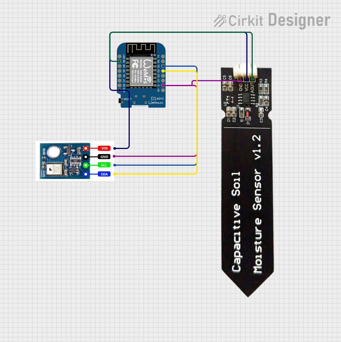
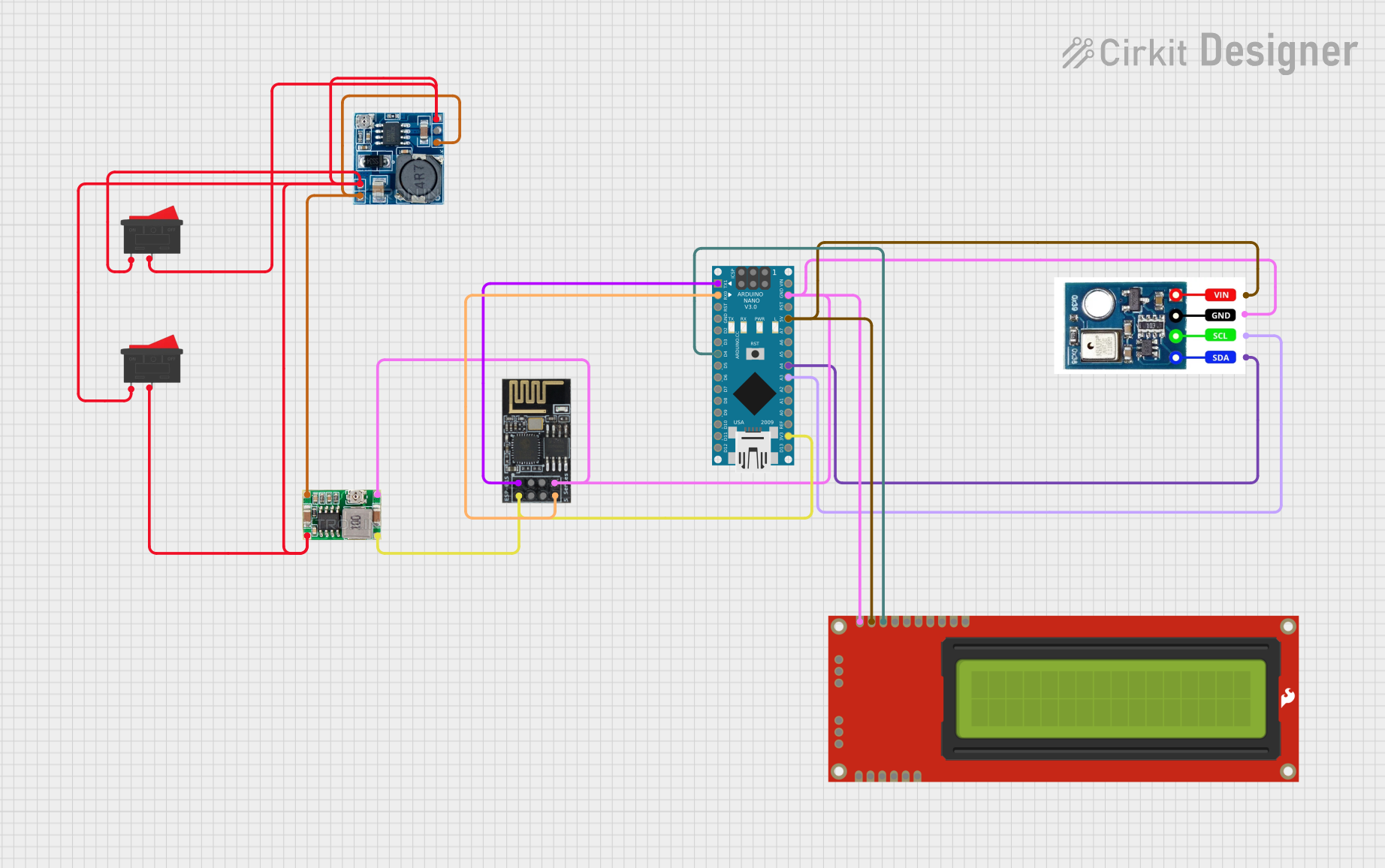
Explore Projects Built with AHT10
Technical Specifications
Key Technical Details
| Parameter | Value |
|---|---|
| Supply Voltage | 2.0V to 5.5V |
| Operating Current | 0.25mA (measuring) |
| Standby Current | 0.01µA |
| Temperature Range | -40°C to 85°C |
| Temperature Accuracy | ±0.3°C |
| Humidity Range | 0% to 100% RH |
| Humidity Accuracy | ±2% RH |
| Interface | I2C |
| I2C Address | 0x38 |
Pin Configuration and Descriptions
| Pin Number | Pin Name | Description |
|---|---|---|
| 1 | VCC | Power supply (2.0V to 5.5V) |
| 2 | GND | Ground |
| 3 | SCL | I2C clock line |
| 4 | SDA | I2C data line |
Usage Instructions
How to Use the AHT10 in a Circuit
- Power Supply: Connect the VCC pin to a 3.3V or 5V power supply and the GND pin to the ground.
- I2C Interface: Connect the SCL pin to the I2C clock line of your microcontroller and the SDA pin to the I2C data line.
- Pull-up Resistors: Ensure that the I2C lines (SCL and SDA) have pull-up resistors (typically 4.7kΩ) connected to the power supply.
Important Considerations and Best Practices
- Power Supply: Ensure a stable power supply to avoid measurement inaccuracies.
- I2C Address: The default I2C address for the AHT10 is 0x38. Ensure no address conflicts on the I2C bus.
- Environmental Factors: Avoid placing the sensor in direct sunlight or near heat sources to prevent skewed readings.
Example Code for Arduino UNO
#include <Wire.h>
#include <AHT10.h>

AHT10 aht10;

void setup() {
  Serial.begin(9600);
  Wire.begin();

  if (aht10.begin()) {
    Serial.println("AHT10 initialized successfully");
  } else {
    Serial.println("AHT10 initialization failed");
  }
}

void loop() {
  float temperature = aht10.readTemperature();
  float humidity = aht10.readHumidity();

  Serial.print("Temperature: ");
  Serial.print(temperature);
  Serial.println(" °C");

  Serial.print("Humidity: ");
  Serial.print(humidity);
  Serial.println(" %");

  delay(2000); // Wait for 2 seconds before the next reading
}
Troubleshooting and FAQs
Common Issues and Solutions
Sensor Not Initializing:
- Issue: The sensor fails to initialize.
- Solution: Check the wiring connections, ensure the power supply is stable, and verify the I2C address.
Inaccurate Readings:
- Issue: The sensor provides inaccurate temperature or humidity readings.
- Solution: Ensure the sensor is not exposed to direct sunlight or heat sources. Verify that the power supply voltage is within the specified range.
I2C Communication Failure:
- Issue: The microcontroller cannot communicate with the sensor.
- Solution: Check the pull-up resistors on the I2C lines. Ensure there are no address conflicts on the I2C bus.
FAQs
Q: What is the default I2C address of the AHT10?
- A: The default I2C address is 0x38.
Q: Can the AHT10 operate at 5V?
- A: Yes, the AHT10 can operate with a supply voltage ranging from 2.0V to 5.5V.
Q: How often should I take readings from the AHT10?
- A: It is recommended to take readings at intervals of at least 2 seconds to ensure accurate measurements.
This documentation provides a comprehensive guide to using the AHT10 temperature and humidity sensor. Whether you are a beginner or an experienced user, following these instructions and best practices will help you achieve accurate and reliable environmental monitoring.