How to Use Adafruit PowerBoost 1000C with Terminal Block: Examples, Pinouts, and Specs
Introduction
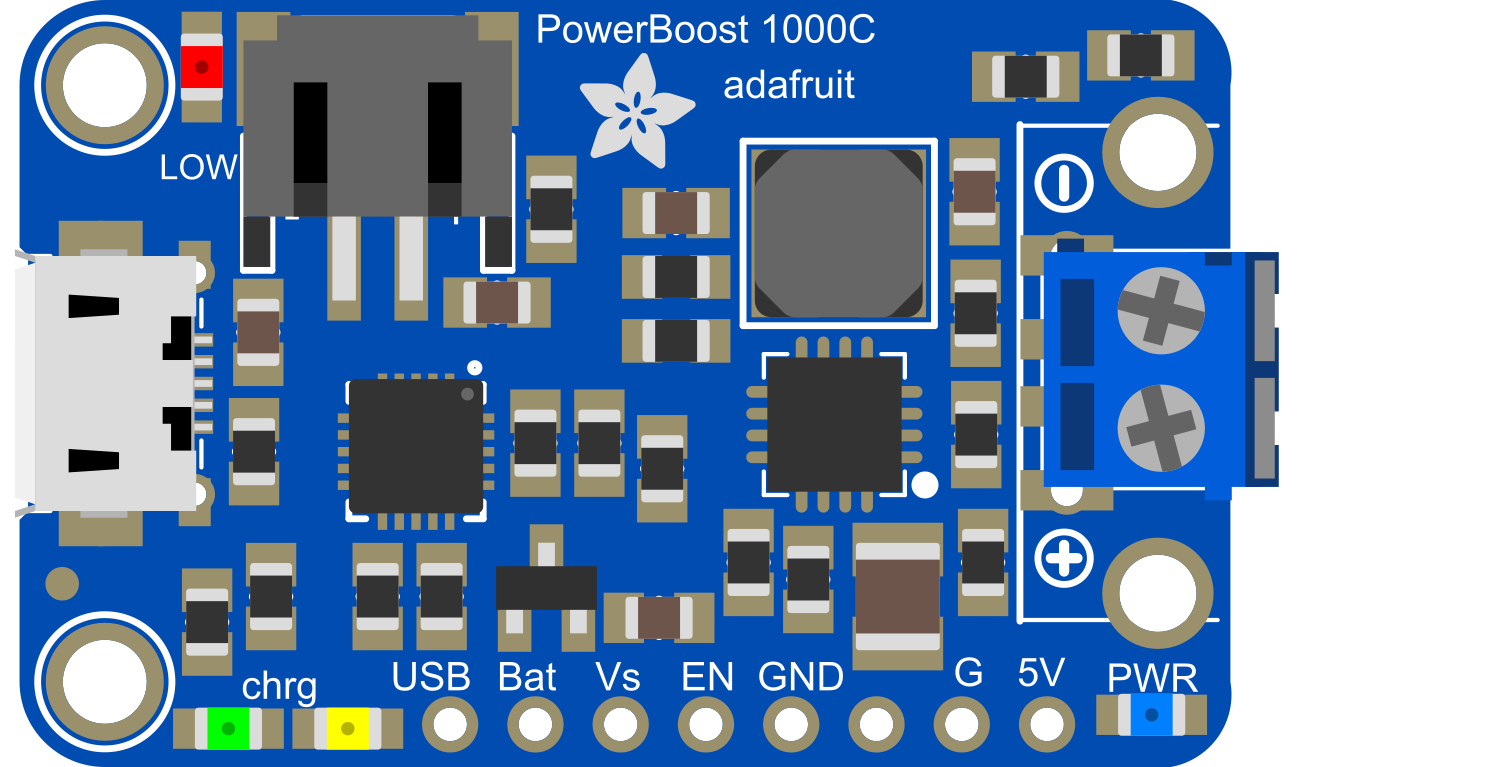
The Adafruit PowerBoost 1000C with Terminal Block is a versatile power supply module designed for electronics enthusiasts and professionals alike. This board is capable of boosting battery voltages to 5V, allowing you to power USB devices from a single lithium polymer or lithium-ion battery. With the addition of a terminal block, it provides a convenient method for connecting power inputs and outputs without the need for a USB port, making it ideal for high-current applications or scenarios where USB connectivity is not feasible.
Explore Projects Built with Adafruit PowerBoost 1000C with Terminal Block
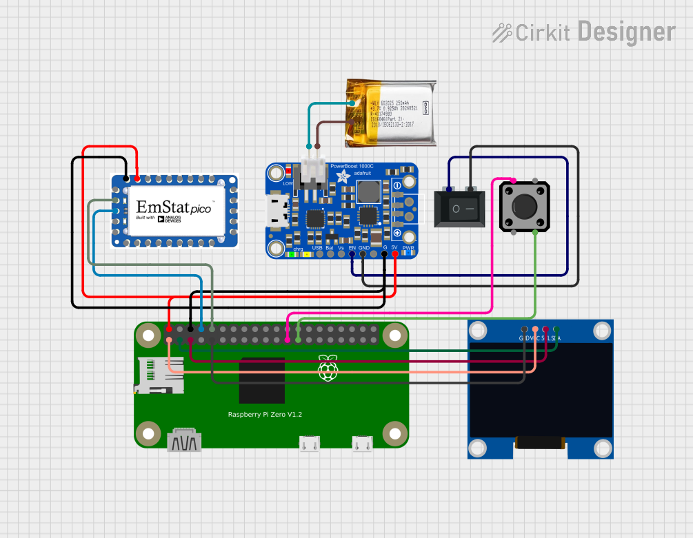

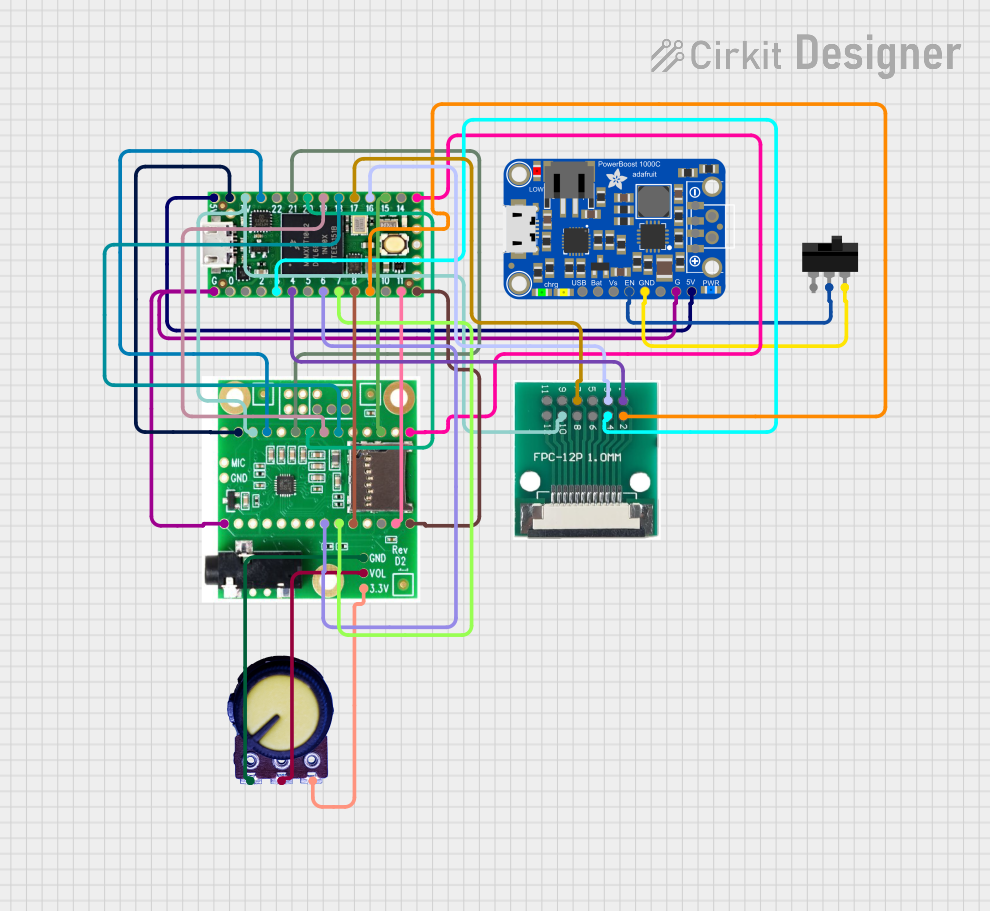

Explore Projects Built with Adafruit PowerBoost 1000C with Terminal Block
Common Applications and Use Cases
- Portable USB chargers for smartphones, tablets, and other devices
- Battery-powered electronics projects
- Wearable electronics with higher current demands
- DIY power banks
- Robotics and remote-controlled devices
Technical Specifications
Key Technical Details
- Input Voltage: 3.7V nominal (for LiPo/Li-Ion batteries)
- Output Voltage: 5V regulated output
- Maximum Output Current: 1A continuous, 2A peak
- Efficiency: 90%+ for most of the battery charge
- Battery Charging: 500mA or 1000mA selectable charge rate
- Low Battery Indicator: LED lights up at around 3.2V
- Integrated Protection: Over-charge/discharge, over-current, and temperature protection
Pin Configuration and Descriptions
| Pin Name | Description |
|---|---|
| BAT | Battery input terminal for LiPo/Li-Ion |
| GND | Ground connection |
| 5V | Regulated 5V output |
| EN | Enable pin for the regulator (active high) |
| LBO | Low Battery Output (active low) |
Usage Instructions
How to Use the Component in a Circuit
Connecting the Battery:
- Connect the positive terminal of the LiPo/Li-Ion battery to the
BATterminal. - Connect the negative terminal of the battery to the
GNDterminal.
- Connect the positive terminal of the LiPo/Li-Ion battery to the
Powering a Device:
- Connect the positive lead of your device to the
5Vterminal. - Connect the negative lead of your device to the
GNDterminal.
- Connect the positive lead of your device to the
Enabling/Disabling Power Output:
- To enable the 5V output, connect the
ENpin toGND. - To disable the 5V output, leave the
ENpin floating (not connected).
- To enable the 5V output, connect the
Important Considerations and Best Practices
- Ensure that the battery voltage does not exceed the recommended input voltage range.
- Do not exceed the maximum output current to prevent overheating and potential damage.
- Use proper gauge wires for high-current connections to minimize voltage drop and heat generation.
- Charge the battery with caution and monitor for overheating, especially if selecting the higher charge rate.
Troubleshooting and FAQs
Common Issues
- Device not powering on: Check battery connections and charge level. Ensure the
ENpin is correctly configured. - Low output voltage: Ensure the battery is not depleted and that the PowerBoost 1000C is not in a low battery state.
- Overheating: Reduce the load if the current draw is too high or improve ventilation around the PowerBoost 1000C.
Solutions and Tips for Troubleshooting
- Battery Issues: If the battery is not charging, check the connections and ensure the battery is not damaged.
- Output Voltage Fluctuations: If the output voltage is unstable, verify that the load does not exceed the maximum rating and that the battery is adequately charged.
- Low Battery Indicator: If the low battery LED is on, recharge the battery to ensure proper operation.
FAQs
Q: Can I use the PowerBoost 1000C to charge my device while simultaneously charging the battery?
- A: Yes, the PowerBoost 1000C supports pass-through charging.
Q: What types of batteries can I use with the PowerBoost 1000C?
- A: The PowerBoost 1000C is designed for use with 3.7V LiPo or Li-Ion batteries.
Q: How do I know if the battery is fully charged?
- A: The onboard charging LED will change from red to green when the battery is fully charged.
Example Code for Arduino UNO
// This example demonstrates how to control the Adafruit PowerBoost 1000C
// with an Arduino UNO for enabling or disabling the 5V output.

const int enablePin = 2; // Connect to the 'EN' pin on PowerBoost 1000C

void setup() {
  pinMode(enablePin, OUTPUT);
  // Start with the PowerBoost 1000C enabled
  digitalWrite(enablePin, LOW);
}

void loop() {
  // This is a simple example to turn off and on the PowerBoost every 5 seconds
  digitalWrite(enablePin, HIGH); // Disable PowerBoost 5V output
  delay(5000);
  digitalWrite(enablePin, LOW); // Enable PowerBoost 5V output
  delay(5000);
}
Remember to keep the code comments concise and within the 80 character line length limit. This example code is a basic demonstration and can be expanded for more complex applications involving the PowerBoost 1000C.