How to Use 2 Gang Outlet: Examples, Pinouts, and Specs
Introduction
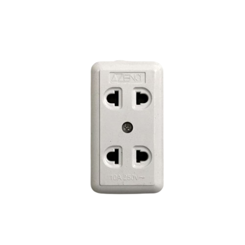
A 2 gang outlet is an electrical receptacle that allows for the connection of two devices simultaneously, providing two separate sockets in a single wall plate. It is a common component in residential, commercial, and industrial electrical systems, offering a convenient way to power multiple devices from a single location.
Explore Projects Built with 2 Gang Outlet


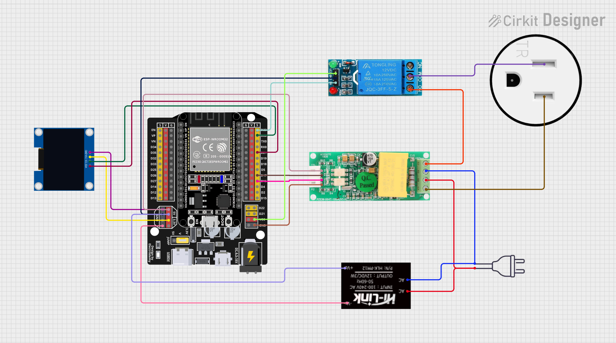

Explore Projects Built with 2 Gang Outlet
Common Applications and Use Cases
- Powering household appliances such as lamps, chargers, and small electronics.
- Providing power to office equipment like computers and printers.
- Supporting industrial tools and machinery in workshops.
- Used in smart home systems for integrating smart plugs or energy monitoring devices.
Technical Specifications
Below are the general technical specifications for a standard 2 gang outlet. Note that specific models may vary slightly depending on the manufacturer.
| Specification | Details |
|---|---|
| Voltage Rating | 120V AC (North America) or 230V AC (Europe and other regions) |
| Current Rating | 15A or 20A (depending on the model and circuit requirements) |
| Frequency | 50Hz or 60Hz (region-dependent) |
| Material | Flame-retardant thermoplastic or metal |
| Mounting Style | Flush-mounted into a standard electrical box |
| Number of Sockets | 2 |
| Grounding | Equipped with a grounding terminal for safety |
| Certifications | UL Listed, CE Mark, or other regional safety certifications |
Pin Configuration and Descriptions
The 2 gang outlet typically has three main terminals for each socket. These terminals are used for wiring the outlet to the electrical system.
| Terminal | Description |
|---|---|
| Hot (Live) | Connects to the live wire (black or brown wire in most systems). |
| Neutral | Connects to the neutral wire (white or blue wire in most systems). |
| Ground | Connects to the ground wire (green or bare copper wire) for safety. |
Usage Instructions
How to Use the Component in a Circuit
- Turn Off Power: Before installation, turn off the power supply at the circuit breaker to avoid electrical shock.
- Prepare the Electrical Box: Ensure the electrical box is properly installed and has enough space for the 2 gang outlet.
- Connect the Wires:
- Strip about 1/2 inch of insulation from the ends of the wires.
- Connect the live wire to the hot terminal, the neutral wire to the neutral terminal, and the ground wire to the ground terminal.
- Tighten the screws securely to ensure a solid connection.
- Mount the Outlet: Secure the outlet into the electrical box using the provided screws.
- Attach the Wall Plate: Install the wall plate over the outlet and secure it with screws.
- Restore Power: Turn the power back on at the circuit breaker and test the outlet with a voltage tester or by plugging in a device.
Important Considerations and Best Practices
- Always follow local electrical codes and regulations when installing or replacing a 2 gang outlet.
- Use outlets with the appropriate current rating (15A or 20A) for the circuit.
- Ensure the outlet is properly grounded to prevent electrical hazards.
- If installing in a damp or outdoor location, use a weatherproof outlet and cover.
- For smart home integration, consider using a 2 gang smart outlet with Wi-Fi or Zigbee compatibility.
Arduino Integration
While a 2 gang outlet is not directly connected to an Arduino, it can be used in conjunction with a relay module to control AC devices. Below is an example of Arduino code to control a device connected to a 2 gang outlet via a relay.
// Example: Controlling a device connected to a 2 gang outlet using a relay module
// Pin 7 is connected to the relay module's control pin

const int relayPin = 7; // Define the relay control pin

void setup() {
  pinMode(relayPin, OUTPUT); // Set the relay pin as an output
  digitalWrite(relayPin, LOW); // Ensure the relay is off initially
}

void loop() {
  digitalWrite(relayPin, HIGH); // Turn on the relay (device powered)
  delay(5000); // Keep the device on for 5 seconds
  digitalWrite(relayPin, LOW); // Turn off the relay (device off)
  delay(5000); // Keep the device off for 5 seconds
}
Note: Ensure proper isolation between the low-voltage Arduino circuit and the high-voltage AC circuit when using a relay.
Troubleshooting and FAQs
Common Issues Users Might Face
Outlet Not Working:
- Cause: Loose or incorrect wiring.
- Solution: Double-check the wiring connections and ensure they are secure and correct.
Tripped Circuit Breaker:
- Cause: Overloading the circuit or a short circuit.
- Solution: Reduce the load on the circuit or inspect for wiring faults.
Sparks When Plugging In Devices:
- Cause: Worn-out outlet contacts or loose wiring.
- Solution: Replace the outlet if it is damaged or worn out.
Device Not Receiving Power:
- Cause: Faulty outlet or no power supply to the circuit.
- Solution: Test the outlet with a voltage tester and check the circuit breaker.
Solutions and Tips for Troubleshooting
- Use a multimeter to verify voltage at the outlet terminals.
- Ensure the outlet is compatible with the voltage and current requirements of your devices.
- If unsure about installation or troubleshooting, consult a licensed electrician.
- Regularly inspect outlets for signs of wear, damage, or overheating.
By following this documentation, users can safely and effectively install and use a 2 gang outlet in their electrical systems.