Cirkit Designer Logo
Cirkit Designer
Your all-in-one circuit design IDE
Home / 
Component Documentation

How to Use Flame Sensor: Examples, Pinouts, and Specs

Image of Flame Sensor
Cirkit Designer LogoDesign with Flame Sensor in Cirkit Designer

Introduction

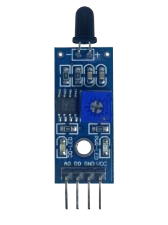
A flame sensor is an electronic device designed to detect the presence of a flame or fire, providing an essential safety feature for various applications. It is commonly used in gas-powered appliances like furnaces, water heaters, and boilers, as well as in fire detection systems for buildings and industrial environments. The sensor's ability to detect flames ensures that fuel is not released without ignition, preventing the accumulation of unburned gas and potential hazards.

Explore Projects Built with Flame Sensor

Use Cirkit Designer to design, explore, and prototype these projects online. Some projects support real-time simulation. Click "Open Project" to start designing instantly!
Arduino UNO Based Multi-Flame Sensor Detection System
Image of flame sensor: A project utilizing Flame Sensor in a practical application
This circuit is designed to monitor for the presence of flames using three flame sensors connected to an Arduino UNO. Each flame sensor's analog output is connected to a separate analog input on the Arduino, allowing the microcontroller to read the intensity of the flame detected by each sensor. The 5V and GND pins of the Arduino provide power to the flame sensors.
Cirkit Designer LogoOpen Project in Cirkit Designer
Flame Detection and Automatic Water Pump Activation System
Image of FIRE: A project utilizing Flame Sensor in a practical application
This circuit features a heat flame sensor that likely triggers a response when detecting heat or flame. The sensor's digital output (DO) is connected through a resistor to a TIP41C transistor, which acts as a switch for a buzzer and a water pump, indicating that the circuit is designed to sound an alarm and possibly activate a water pump in the event of detecting a flame. The 9V battery powers the circuit, and all components share a common ground.
Cirkit Designer LogoOpen Project in Cirkit Designer
Arduino UNO-Based Environmental Monitoring System with Wi-Fi Connectivity
Image of fire and smoke detection: A project utilizing Flame Sensor in a practical application
This circuit is designed to monitor environmental conditions using a heat flame sensor and an MQ135 air quality sensor, display information on an LCD screen, and maintain accurate time with an RTC module. It includes an ESP8266 Wi-Fi module for potential wireless connectivity and uses a buzzer and LED for alerts or status indications. The Arduino UNO serves as the central controller, though the specific embedded code for operation is not yet provided.
Cirkit Designer LogoOpen Project in Cirkit Designer
Arduino UNO Based Gas and Flame Detection System with I2C LCD Feedback and Alert Buzzer
Image of SCHEMATIC DIAGRAM PROJECT 2: A project utilizing Flame Sensor in a practical application
This circuit features an Arduino UNO microcontroller connected to a heat flame sensor and an MQ-2 gas sensor for detecting flames and gases, respectively. The Arduino is also interfaced with an I2C LCD 16x2 screen for displaying sensor readings or status messages. Additionally, there is a buzzer connected to the Arduino, which can be used for audible alerts or alarms based on sensor inputs.
Cirkit Designer LogoOpen Project in Cirkit Designer

Explore Projects Built with Flame Sensor

Use Cirkit Designer to design, explore, and prototype these projects online. Some projects support real-time simulation. Click "Open Project" to start designing instantly!
Image of flame sensor: A project utilizing Flame Sensor in a practical application
Arduino UNO Based Multi-Flame Sensor Detection System
This circuit is designed to monitor for the presence of flames using three flame sensors connected to an Arduino UNO. Each flame sensor's analog output is connected to a separate analog input on the Arduino, allowing the microcontroller to read the intensity of the flame detected by each sensor. The 5V and GND pins of the Arduino provide power to the flame sensors.
Cirkit Designer LogoOpen Project in Cirkit Designer
Image of FIRE: A project utilizing Flame Sensor in a practical application
Flame Detection and Automatic Water Pump Activation System
This circuit features a heat flame sensor that likely triggers a response when detecting heat or flame. The sensor's digital output (DO) is connected through a resistor to a TIP41C transistor, which acts as a switch for a buzzer and a water pump, indicating that the circuit is designed to sound an alarm and possibly activate a water pump in the event of detecting a flame. The 9V battery powers the circuit, and all components share a common ground.
Cirkit Designer LogoOpen Project in Cirkit Designer
Image of fire and smoke detection: A project utilizing Flame Sensor in a practical application
Arduino UNO-Based Environmental Monitoring System with Wi-Fi Connectivity
This circuit is designed to monitor environmental conditions using a heat flame sensor and an MQ135 air quality sensor, display information on an LCD screen, and maintain accurate time with an RTC module. It includes an ESP8266 Wi-Fi module for potential wireless connectivity and uses a buzzer and LED for alerts or status indications. The Arduino UNO serves as the central controller, though the specific embedded code for operation is not yet provided.
Cirkit Designer LogoOpen Project in Cirkit Designer
Image of SCHEMATIC DIAGRAM PROJECT 2: A project utilizing Flame Sensor in a practical application
Arduino UNO Based Gas and Flame Detection System with I2C LCD Feedback and Alert Buzzer
This circuit features an Arduino UNO microcontroller connected to a heat flame sensor and an MQ-2 gas sensor for detecting flames and gases, respectively. The Arduino is also interfaced with an I2C LCD 16x2 screen for displaying sensor readings or status messages. Additionally, there is a buzzer connected to the Arduino, which can be used for audible alerts or alarms based on sensor inputs.
Cirkit Designer LogoOpen Project in Cirkit Designer

Common Applications and Use Cases

  • Gas-powered appliances (furnaces, water heaters, stoves)
  • Fire alarm systems
  • Industrial safety systems
  • Robotics (fire-fighting robots)
  • Environmental monitoring

Technical Specifications

Key Technical Details

  • Operating Voltage: Typically 3.3V to 5V
  • Current Consumption: 15mA (typical)
  • Spectral Sensitivity: 760nm to 1100nm (infrared spectrum)
  • Detection Angle: Approximately 60 degrees
  • Operating Temperature Range: -25°C to 85°C

Pin Configuration and Descriptions

Pin Number Name Description
1 VCC Connect to 3.3V or 5V power supply
2 GND Connect to ground
3 DO Digital output; goes high when flame is detected
4 AO Analog output; voltage level indicates flame intensity

Usage Instructions

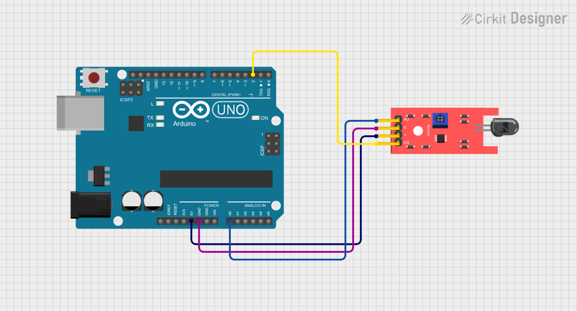
How to Use the Flame Sensor in a Circuit

  1. Power Connections: Connect the VCC pin to a 3.3V or 5V power supply and the GND pin to the ground.
  2. Output Connections: Connect the DO pin to a digital input pin on your microcontroller if you want a simple high/low signal. For an analog signal that represents the intensity of the flame, connect the AO pin to an analog input pin.
  3. Adjust Sensitivity: Many flame sensors come with a potentiometer to adjust sensitivity. Turn the potentiometer until the sensor outputs a high signal only when a flame is present at the desired distance.

Important Considerations and Best Practices

  • Distance from Flame: The sensor should be placed at a safe distance from the flame to avoid damage.
  • Ambient Light: Be aware of ambient light that may affect the sensor's readings.
  • Interference: Other infrared sources can interfere with the sensor's ability to detect flames accurately.
  • Testing: Regularly test the sensor to ensure it is functioning correctly.

Example Code for Arduino UNO

// Define the digital and analog pin connected to the flame sensor
#define FLAME_SENSOR_DIGITAL_PIN 2
#define FLAME_SENSOR_ANALOG_PIN A0

void setup() {
  pinMode(FLAME_SENSOR_DIGITAL_PIN, INPUT);
  Serial.begin(9600);
}

void loop() {
  int analogValue = analogRead(FLAME_SENSOR_ANALOG_PIN);
  int digitalValue = digitalRead(FLAME_SENSOR_DIGITAL_PIN);

  // Print the analog value to the Serial Monitor
  Serial.print("Analog Value: ");
  Serial.print(analogValue);

  // Check if the digital output is high (flame detected)
  if (digitalValue == HIGH) {
    Serial.println(" - Flame detected!");
  } else {
    Serial.println(" - No flame detected.");
  }

  // Wait for a short period before reading again
  delay(500);
}

Troubleshooting and FAQs

Common Issues

  • Sensor Not Responding: Ensure that the sensor is correctly powered and that the pins are connected properly.
  • False Alarms: Adjust the sensitivity potentiometer, shield the sensor from ambient light, or reposition the sensor to avoid other infrared sources.
  • No Flame Detection: Check the distance between the sensor and the flame. It may be too far or too close.

Solutions and Tips for Troubleshooting

  • Check Connections: Verify all connections are secure and correct.
  • Adjust Sensitivity: Use the onboard potentiometer to fine-tune the sensor's sensitivity.
  • Test with Known Sources: Use a consistent flame source, like a lighter, to test the sensor's functionality.

FAQs

Q: Can the flame sensor detect flames through glass? A: No, the sensor cannot detect flames through glass as it typically blocks the infrared wavelengths the sensor detects.

Q: How can I increase the range of detection? A: Adjust the sensitivity potentiometer carefully. However, increasing the range may also increase the likelihood of false positives.

Q: Is the flame sensor waterproof? A: Generally, flame sensors are not waterproof. Protect the sensor from moisture to ensure proper operation.

Q: Can the sensor differentiate between different types of flames? A: No, the sensor cannot differentiate between types of flames; it only detects the presence of a flame within its spectral sensitivity range.