How to Use SimpleFOCMini: Examples, Pinouts, and Specs
Introduction
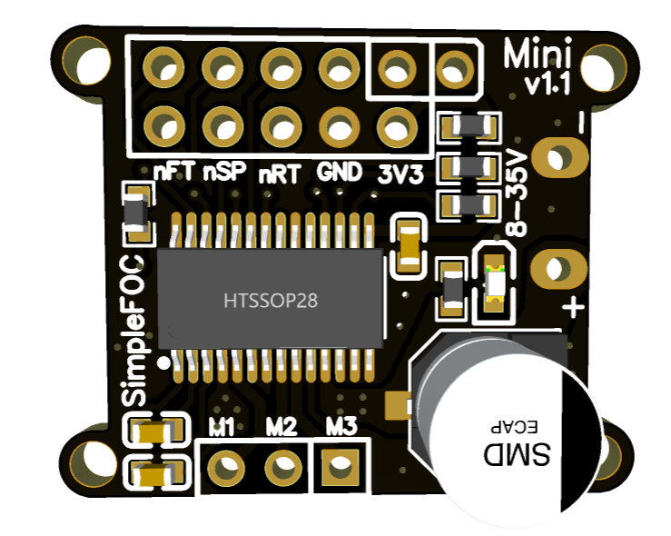
The SimpleFOCMini is a compact and versatile 3-phase motor controller designed to implement Field-Oriented Control (FOC) for Brushless DC (BLDC) and Permanent Magnet Synchronous Motors (PMSM). This controller is ideal for precision motor control applications, such as robotics, drones, and automation systems, where smooth and efficient operation is required.
Explore Projects Built with SimpleFOCMini
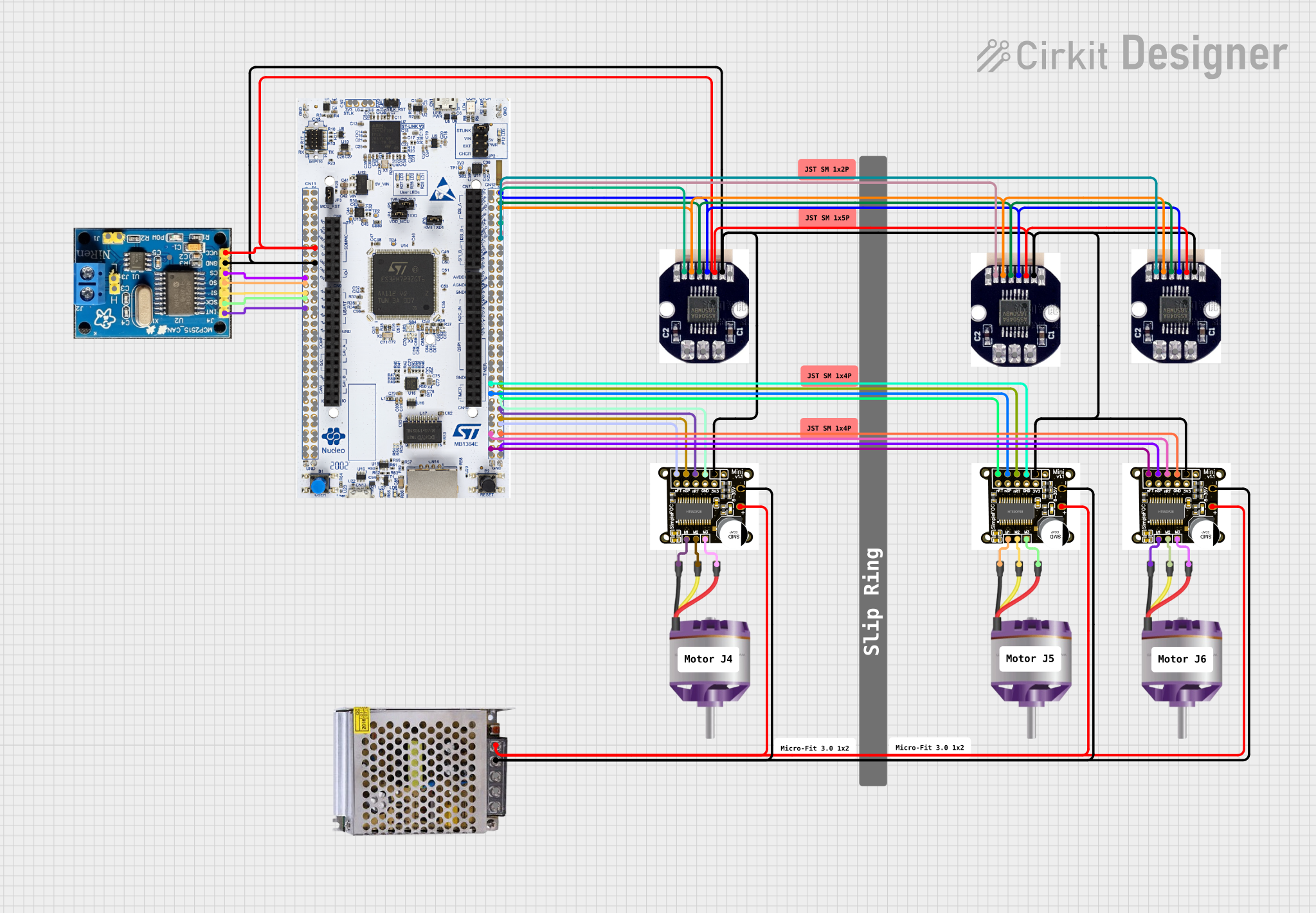

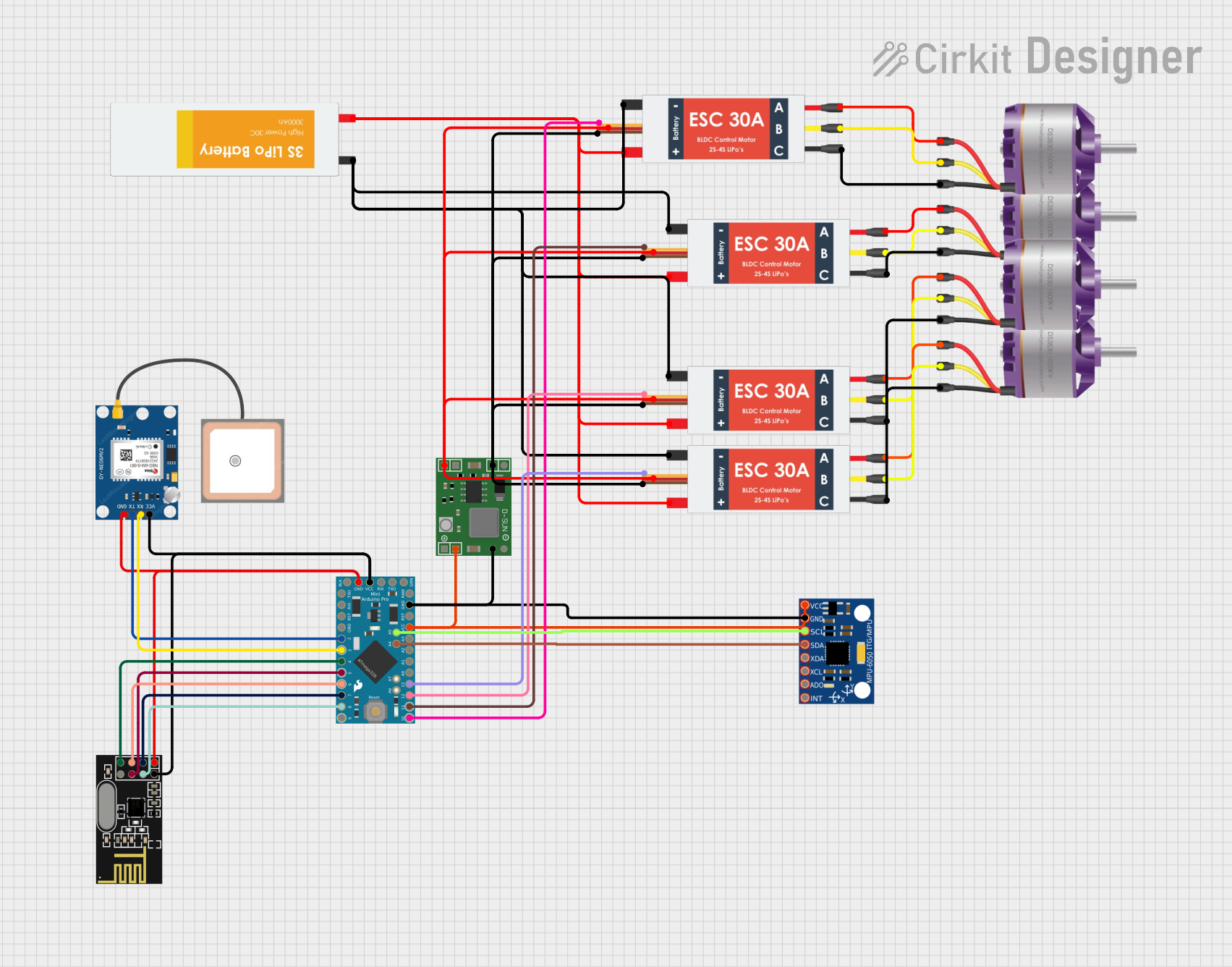
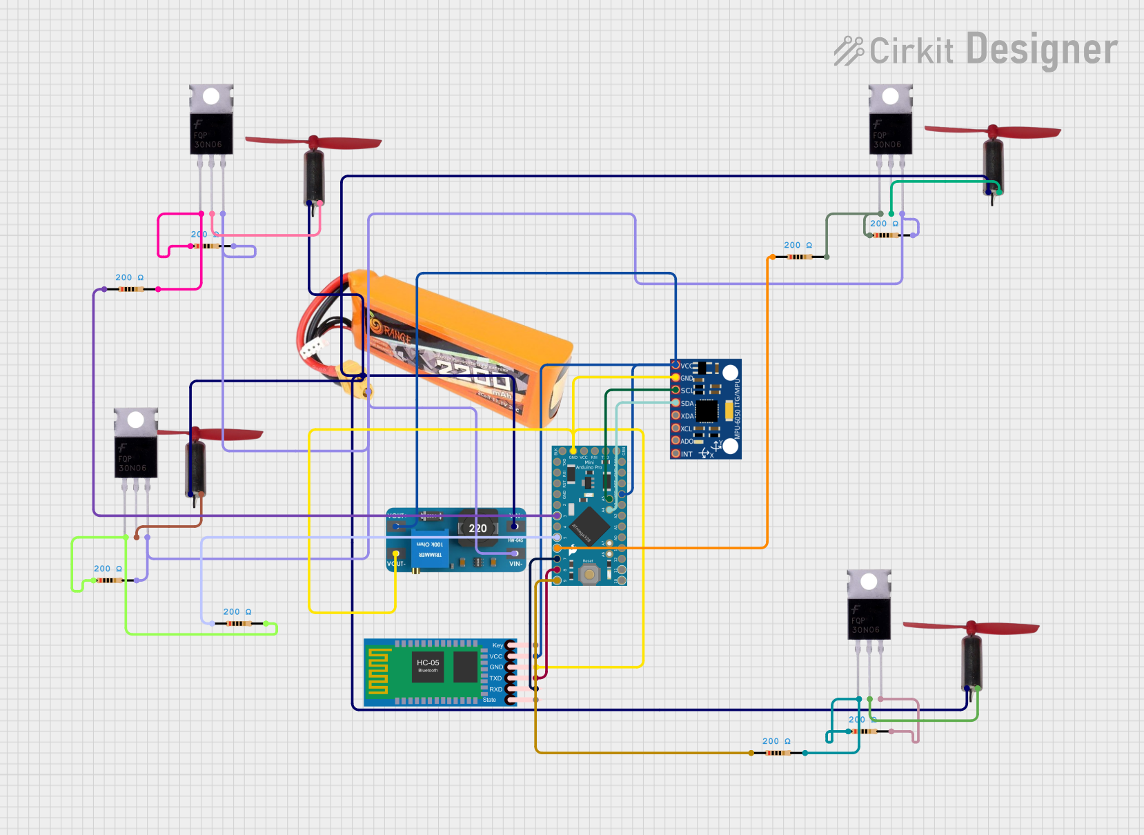
Explore Projects Built with SimpleFOCMini
Technical Specifications
Key Technical Details
- Voltage Range: 6V - 30V
- Continuous Current: Up to 3A
- Peak Current: Up to 5A (short duration)
- PWM Frequency: Up to 40kHz
- MCU: STM32G431 (32-bit ARM Cortex-M4)
- Communication: UART, I2C, SPI, PWM, Analog
- Encoder Support: ABI, UVW, Hall sensors
- Sensorless Support: Yes, with back EMF sensing
Pin Configuration and Descriptions
| Pin Number | Pin Name | Description |
|---|---|---|
| 1 | GND | Ground connection |
| 2 | VIN | Voltage input (6V-30V) |
| 3 | OUTA | Phase A motor output |
| 4 | OUTB | Phase B motor output |
| 5 | OUTC | Phase C motor output |
| 6 | EN | Enable pin (active high) |
| 7 | TEMP | Temperature sensor output |
| 8 | AN | Analog input for current sensing |
| 9 | SCL | I2C clock line |
| 10 | SDA | I2C data line |
| 11 | TX | UART transmit |
| 12 | RX | UART receive |
| 13 | SWDIO | Serial Wire Debug Data I/O |
| 14 | SWCLK | Serial Wire Debug Clock |
Usage Instructions
Connecting the SimpleFOCMini to a Motor
- Connect the motor phase wires to the OUTA, OUTB, and OUTC pins on the SimpleFOCMini.
- Ensure that the power supply voltage is within the specified range (6V-30V) and connect it to the VIN and GND pins.
- If using an encoder or Hall sensors, connect them to the appropriate pins as per the sensor's datasheet.
Programming and Configuration
To control the SimpleFOCMini with an Arduino UNO, follow these steps:
- Install the SimpleFOC library using the Arduino Library Manager.
- Connect the SimpleFOCMini to the Arduino UNO via UART, I2C, or SPI.
- Use the following sample code to initialize the motor and set up the control loop:
#include <SimpleFOC.h>

// Motor instance
BLDCMotor motor = BLDCMotor(pole_pairs);
BLDCDriver3PWM driver = BLDCDriver3PWM(pwmA, pwmB, pwmC, en);

void setup() {
  // Motor & driver setup
  motor.linkDriver(&driver);
  motor.voltage_limit = 12; // Voltage limit in volts
  motor.velocity_limit = 5; // Velocity limit in rad/s

  // Initialize motor and driver
  motor.init();
  driver.init();

  // Set the initial target velocity
  motor.target_velocity = 1;

  // Enable motor
  driver.voltage_power_supply = 12;
  driver.enable();
}

void loop() {
  // FOC algorithm iteration
  motor.loopFOC();

  // Motion control loop
  motor.move();
}
Important Considerations and Best Practices
- Always ensure the power supply is disconnected before making any connections to the motor or sensors.
- Use appropriate gauge wires for motor connections to handle the expected current.
- Implement proper cooling if operating the controller at high currents for extended periods.
- Use filtering capacitors close to the controller's power input to reduce voltage spikes and electrical noise.
Troubleshooting and FAQs
Common Issues
- Motor not spinning: Check connections, ensure power supply is within range, and verify that the motor parameters are correctly set in the software.
- Overheating: Ensure adequate cooling, check for shorts, and verify that the current limits are not exceeded.
- Communication failure: Check wiring for UART, I2C, or SPI and ensure that the correct communication protocol and settings are used in the software.
Solutions and Tips
- Motor stuttering: This can be due to incorrect encoder readings or misconfiguration of the motor parameters. Double-check the encoder connections and motor specifications.
- No response to commands: Verify that the enable pin (EN) is set high and that the controller is receiving the correct control signals.
FAQs
Q: Can the SimpleFOCMini be used without an encoder? A: Yes, the SimpleFOCMini supports sensorless operation using back EMF sensing.
Q: What is the maximum PWM frequency supported by the SimpleFOCMini? A: The maximum PWM frequency is 40kHz.
Q: How do I update the firmware on the SimpleFOCMini? A: Firmware updates can be done via the Serial Wire Debug (SWD) interface using compatible programming tools.
For further assistance, please refer to the SimpleFOC community forums or contact technical support.