Cirkit Designer
Your all-in-one circuit design IDE
Home /
Component Documentation
How to Use WiFi Transceiver: Examples, Pinouts, and Specs
Introduction
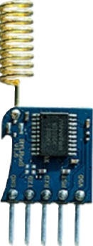
The REYAX RYLR998 is a high-performance WiFi transceiver module designed to enable wireless communication by transmitting and receiving data over WiFi networks. This compact and versatile device allows devices to connect to the internet or communicate with each other seamlessly. It is widely used in IoT applications, smart home devices, industrial automation, and wireless sensor networks.
Explore Projects Built with WiFi Transceiver
ESP32-Based RF Communication System with 433 MHz Modules

This circuit comprises an ESP32 microcontroller connected to a 433 MHz RF transmitter and receiver pair. The ESP32 is programmed to receive and decode RF signals through the receiver module, as well as send RF signals via the transmitter module. Additionally, the ESP32 can communicate with a Bluetooth device to exchange commands and data, and it uses an LED for status indication.
433 MHz RF Transmitter and Receiver with Arduino UNO for Wireless Communication

This circuit consists of two Arduino UNO microcontrollers, each connected to an RF 433 MHz Transmitter and a 433 MHz RF Receiver Module. The setup allows for wireless communication between the two Arduinos, enabling them to send and receive data over a 433 MHz RF link.
Arduino Nano and NRF24L01 Wireless Communication Module
This circuit features an Arduino Nano microcontroller interfaced with an NRF24L01 wireless transceiver module via an adapter. The setup is designed for wireless communication, with the Arduino controlling the transceiver through SPI and digital I/O pins, and the code provided is a basic template for further development.
Battery-Powered nRF52840 and HT-RA62 Communication Module

This circuit is a wireless communication system powered by a 18650 Li-ion battery, featuring an nRF52840 ProMicro microcontroller and an HT-RA62 transceiver module. The nRF52840 handles the control logic and interfaces with the HT-RA62 for data transmission, while the battery provides the necessary power for the entire setup.
Explore Projects Built with WiFi Transceiver
ESP32-Based RF Communication System with 433 MHz Modules
This circuit comprises an ESP32 microcontroller connected to a 433 MHz RF transmitter and receiver pair. The ESP32 is programmed to receive and decode RF signals through the receiver module, as well as send RF signals via the transmitter module. Additionally, the ESP32 can communicate with a Bluetooth device to exchange commands and data, and it uses an LED for status indication.
433 MHz RF Transmitter and Receiver with Arduino UNO for Wireless Communication
This circuit consists of two Arduino UNO microcontrollers, each connected to an RF 433 MHz Transmitter and a 433 MHz RF Receiver Module. The setup allows for wireless communication between the two Arduinos, enabling them to send and receive data over a 433 MHz RF link.
Arduino Nano and NRF24L01 Wireless Communication Module
This circuit features an Arduino Nano microcontroller interfaced with an NRF24L01 wireless transceiver module via an adapter. The setup is designed for wireless communication, with the Arduino controlling the transceiver through SPI and digital I/O pins, and the code provided is a basic template for further development.
Battery-Powered nRF52840 and HT-RA62 Communication Module
This circuit is a wireless communication system powered by a 18650 Li-ion battery, featuring an nRF52840 ProMicro microcontroller and an HT-RA62 transceiver module. The nRF52840 handles the control logic and interfaces with the HT-RA62 for data transmission, while the battery provides the necessary power for the entire setup.
Common Applications
- Internet of Things (IoT) devices
- Smart home automation systems
- Wireless data logging and monitoring
- Industrial control systems
- Remote device communication
Technical Specifications
Key Technical Details
| Parameter | Specification |
|---|---|
| Manufacturer | REYAX |
| Part ID | RYLR998 |
| Communication Protocol | WiFi (802.11 b/g/n) |
| Operating Voltage | 3.3V |
| Operating Current | 80mA (typical) |
| Transmission Power | +20 dBm (maximum) |
| Data Rate | Up to 150 Mbps |
| Operating Temperature | -40°C to +85°C |
| Dimensions | 24mm x 16mm x 3mm |
Pin Configuration and Descriptions
The RYLR998 module has a total of 8 pins. Below is the pinout and description:
| Pin Number | Pin Name | Description |
|---|---|---|
| 1 | VCC | Power supply input (3.3V) |
| 2 | GND | Ground |
| 3 | TXD | UART Transmit Data (connect to RX of MCU) |
| 4 | RXD | UART Receive Data (connect to TX of MCU) |
| 5 | EN | Enable pin (active HIGH to enable the module) |
| 6 | RST | Reset pin (active LOW to reset the module) |
| 7 | GPIO0 | General Purpose Input/Output |
| 8 | GPIO1 | General Purpose Input/Output |
Usage Instructions
How to Use the RYLR998 in a Circuit
- Power Supply: Connect the VCC pin to a 3.3V regulated power source and the GND pin to ground.
- UART Communication: Connect the TXD pin of the module to the RX pin of your microcontroller (e.g., Arduino UNO) and the RXD pin of the module to the TX pin of the microcontroller.
- Enable the Module: Pull the EN pin HIGH to activate the module.
- Reset the Module: Optionally, connect the RST pin to a GPIO pin of your microcontroller for manual or software-controlled resets.
- GPIO Pins: Use GPIO0 and GPIO1 for additional control or input/output functionality as needed.
Important Considerations
- Ensure the power supply is stable and within the specified voltage range (3.3V).
- Use level shifters if interfacing with a 5V microcontroller to avoid damaging the module.
- Place decoupling capacitors (e.g., 0.1µF) near the VCC pin to reduce noise.
- Avoid placing the module near sources of electromagnetic interference (EMI) to maintain signal integrity.
Example: Connecting to an Arduino UNO
Below is an example of how to connect the RYLR998 to an Arduino UNO and send data over WiFi.
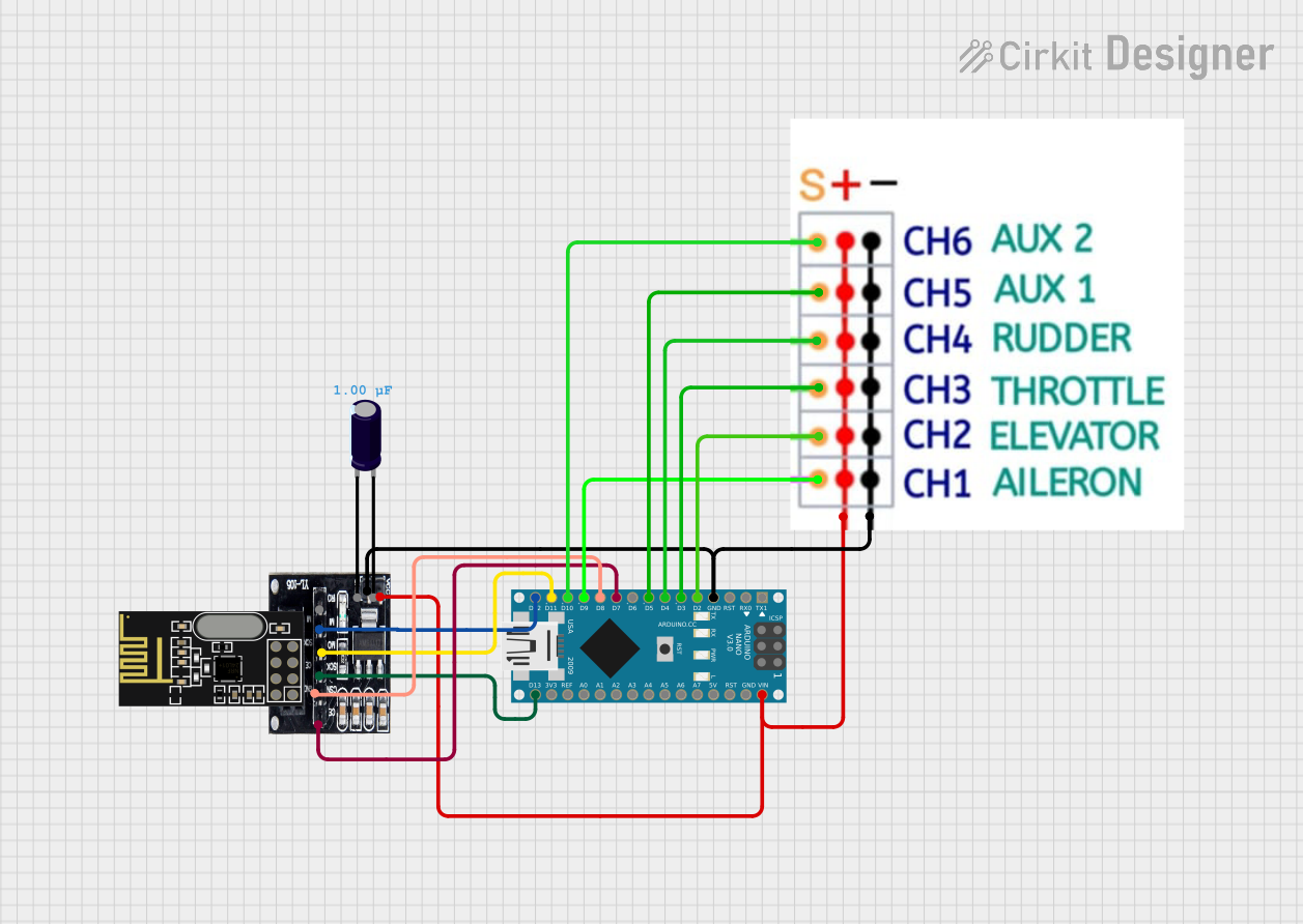
Circuit Diagram
- RYLR998 VCC → 3.3V on Arduino
- RYLR998 GND → GND on Arduino
- RYLR998 TXD → Pin 10 on Arduino (SoftwareSerial RX)
- RYLR998 RXD → Pin 11 on Arduino (SoftwareSerial TX)
- RYLR998 EN → 3.3V
- RYLR998 RST → Digital Pin 9 on Arduino
Arduino Code
#include <SoftwareSerial.h>

// Define SoftwareSerial pins for RYLR998
SoftwareSerial wifiModule(10, 11); // RX = Pin 10, TX = Pin 11

void setup() {
  // Initialize serial communication
  Serial.begin(9600); // For debugging via Serial Monitor
  wifiModule.begin(9600); // Communication with RYLR998

  // Reset the module
  pinMode(9, OUTPUT); // RST pin connected to Digital Pin 9
  digitalWrite(9, LOW); // Pull RST pin LOW to reset
  delay(100); // Wait for reset
  digitalWrite(9, HIGH); // Release reset

  // Send initialization command to the module
  wifiModule.println("AT+RST"); // Reset command
  delay(2000); // Wait for the module to restart

  // Connect to WiFi network
  wifiModule.println("AT+CWJAP=\"YourSSID\",\"YourPassword\"");
  delay(5000); // Wait for connection to establish
}

void loop() {
  // Send data over WiFi
  wifiModule.println("AT+CIPSEND=4"); // Prepare to send 4 bytes
  delay(100);
  wifiModule.println("TEST"); // Send "TEST" data

  // Read and print responses from the module
  while (wifiModule.available()) {
    String response = wifiModule.readString();
    Serial.println(response); // Print response to Serial Monitor
  }

  delay(5000); // Wait before sending the next message
}
Notes
- Replace
"YourSSID"and"YourPassword"with your WiFi network credentials. - Ensure the Arduino IDE Serial Monitor is set to the correct baud rate (9600 in this case).
Troubleshooting and FAQs
Common Issues
Module Not Responding
- Ensure the EN pin is pulled HIGH.
- Verify the power supply is stable and within the 3.3V range.
- Check the UART connections (TXD and RXD) for proper wiring.
WiFi Connection Fails
- Double-check the SSID and password in the code.
- Ensure the WiFi network is within range and not restricted (e.g., MAC filtering).
Data Transmission Errors
- Verify the baud rate settings match between the module and the microcontroller.
- Check for electromagnetic interference near the module.
Tips for Troubleshooting
- Use an oscilloscope or logic analyzer to monitor UART signals for debugging.
- Test the module with simple AT commands (e.g.,
AT,AT+RST) to verify basic functionality. - Refer to the REYAX RYLR998 datasheet for advanced configuration options.