Cirkit Designer Logo
Cirkit Designer
Your all-in-one circuit design IDE
Home / 
Component Documentation

How to Use Sigcom Pull: Examples, Pinouts, and Specs

Image of Sigcom Pull
Cirkit Designer LogoDesign with Sigcom Pull in Cirkit Designer

Introduction

The Sigcom Pull (SG-42SK), manufactured by SIGCOM, is a versatile electronic component designed for use in signal communication systems. It primarily functions as a pull-up or pull-down resistor, ensuring stable signal levels in digital circuits. By maintaining a defined logic state when no active signal is present, the Sigcom Pull prevents floating inputs and improves the reliability of digital systems.

Explore Projects Built with Sigcom Pull

Use Cirkit Designer to design, explore, and prototype these projects online. Some projects support real-time simulation. Click "Open Project" to start designing instantly!
ESP32 with SIMCOM A7672s IoT Sensor Data Logger
Image of LM393 to LilygoSIM7000: A project utilizing Sigcom Pull in a practical application
This circuit integrates an ESP32 with SIMCOM A7672s module with an LM393 comparator for sensor data acquisition. The ESP32 is programmed to read a digital signal from the LM393's D0 output, corresponding to a threshold detection, and then sends this data to the Blynk Cloud using the SIMCOM A7672s module for remote monitoring. The LM393 is powered by the ESP32's 3.3V supply, and both share a common ground.
Cirkit Designer LogoOpen Project in Cirkit Designer
Battery-Powered Arduino Nano IoT Device with SIM800L and MPU6050
Image of Accedent Detection System: A project utilizing Sigcom Pull in a practical application
This circuit integrates an Arduino Nano with an MPU6050 accelerometer and gyroscope sensor and a SIM800L GSM module. The Arduino reads sensor data from the MPU6050 via I2C and communicates with the SIM800L for GSM functionalities. Power is managed through a 7805 voltage regulator, converting 3.7V battery input to 5V for the components.
Cirkit Designer LogoOpen Project in Cirkit Designer
Cellular-Connected ESP32-CAM with Real-Time Clock and Isolated Control
Image of LRCM PHASE 2 PRO: A project utilizing Sigcom Pull in a practical application
This circuit integrates a LilyGo-SIM7000G module with an RTC DS3231 for timekeeping, interfaced via I2C (SCL and SDA lines). An 8-Channel OPTO-COUPLER is used to isolate and interface external signals with the LilyGo-SIM7000G's GPIOs. Power is managed by a Buck converter, which steps down voltage from a DC Power Source to supply the ESP32-CAM and LilyGo-SIM7000G modules, as well as the OPTO-COUPLER.
Cirkit Designer LogoOpen Project in Cirkit Designer
Wi-Fi and GSM Controlled Smart Relay with LCD Display
Image of izdelie_2: A project utilizing Sigcom Pull in a practical application
This circuit integrates an ESP8266 WiFi module, a SIM800c GSM module, and a 16x2 LCD display to create a remote-controlled system with a menu interface. The system uses pushbuttons for user input, controls a relay for switching operations, and communicates via MQTT for remote monitoring and control.
Cirkit Designer LogoOpen Project in Cirkit Designer

Explore Projects Built with Sigcom Pull

Use Cirkit Designer to design, explore, and prototype these projects online. Some projects support real-time simulation. Click "Open Project" to start designing instantly!
Image of LM393 to LilygoSIM7000: A project utilizing Sigcom Pull in a practical application
ESP32 with SIMCOM A7672s IoT Sensor Data Logger
This circuit integrates an ESP32 with SIMCOM A7672s module with an LM393 comparator for sensor data acquisition. The ESP32 is programmed to read a digital signal from the LM393's D0 output, corresponding to a threshold detection, and then sends this data to the Blynk Cloud using the SIMCOM A7672s module for remote monitoring. The LM393 is powered by the ESP32's 3.3V supply, and both share a common ground.
Cirkit Designer LogoOpen Project in Cirkit Designer
Image of Accedent Detection System: A project utilizing Sigcom Pull in a practical application
Battery-Powered Arduino Nano IoT Device with SIM800L and MPU6050
This circuit integrates an Arduino Nano with an MPU6050 accelerometer and gyroscope sensor and a SIM800L GSM module. The Arduino reads sensor data from the MPU6050 via I2C and communicates with the SIM800L for GSM functionalities. Power is managed through a 7805 voltage regulator, converting 3.7V battery input to 5V for the components.
Cirkit Designer LogoOpen Project in Cirkit Designer
Image of LRCM PHASE 2 PRO: A project utilizing Sigcom Pull in a practical application
Cellular-Connected ESP32-CAM with Real-Time Clock and Isolated Control
This circuit integrates a LilyGo-SIM7000G module with an RTC DS3231 for timekeeping, interfaced via I2C (SCL and SDA lines). An 8-Channel OPTO-COUPLER is used to isolate and interface external signals with the LilyGo-SIM7000G's GPIOs. Power is managed by a Buck converter, which steps down voltage from a DC Power Source to supply the ESP32-CAM and LilyGo-SIM7000G modules, as well as the OPTO-COUPLER.
Cirkit Designer LogoOpen Project in Cirkit Designer
Image of izdelie_2: A project utilizing Sigcom Pull in a practical application
Wi-Fi and GSM Controlled Smart Relay with LCD Display
This circuit integrates an ESP8266 WiFi module, a SIM800c GSM module, and a 16x2 LCD display to create a remote-controlled system with a menu interface. The system uses pushbuttons for user input, controls a relay for switching operations, and communicates via MQTT for remote monitoring and control.
Cirkit Designer LogoOpen Project in Cirkit Designer

Common Applications and Use Cases

  • Digital signal stabilization in microcontroller circuits
  • Pull-up or pull-down resistor for GPIO pins
  • Noise reduction in high-speed communication lines
  • Ensuring proper logic levels in I2C, SPI, and UART interfaces
  • Used in debounce circuits for mechanical switches

Technical Specifications

Key Technical Details

Parameter Value
Manufacturer SIGCOM
Part Number SG-42SK
Resistance Range 1 kΩ to 100 kΩ
Tolerance ±1%
Maximum Voltage Rating 50 V
Maximum Power Rating 0.25 W (1/4 W)
Operating Temperature -40°C to +125°C
Package Type Through-hole or SMD

Pin Configuration and Descriptions

The Sigcom Pull (SG-42SK) is a two-terminal component. Below is the pin configuration:

Pin Number Pin Name Description
1 Terminal 1 Connect to the signal line or VCC/GND
2 Terminal 2 Connect to the signal line or VCC/GND

Usage Instructions

How to Use the Component in a Circuit

  1. Determine the Required Configuration:

    • For a pull-up resistor, connect one terminal of the Sigcom Pull to the signal line and the other terminal to the positive voltage supply (VCC).
    • For a pull-down resistor, connect one terminal to the signal line and the other terminal to ground (GND).
  2. Select the Appropriate Resistance Value:

    • Choose a resistance value that balances power consumption and signal stability. Common values are 4.7 kΩ or 10 kΩ for digital circuits.
  3. Connect the Component:

    • Solder the Sigcom Pull to the circuit board, ensuring proper orientation and secure connections.
  4. Test the Circuit:

    • Verify that the signal line maintains the desired logic level when no active signal is present.

Important Considerations and Best Practices

  • Avoid Excessive Current: Ensure the resistance value is high enough to limit current flow and prevent damage to the circuit.
  • Check Voltage Ratings: Do not exceed the maximum voltage rating of 50 V.
  • Minimize Noise: Use decoupling capacitors in conjunction with the Sigcom Pull for high-speed circuits to reduce noise.
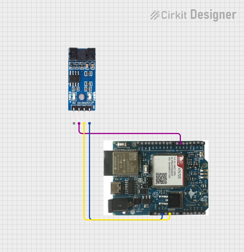
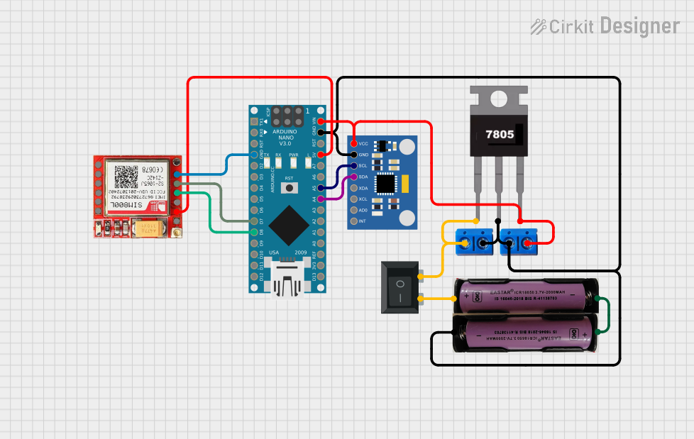
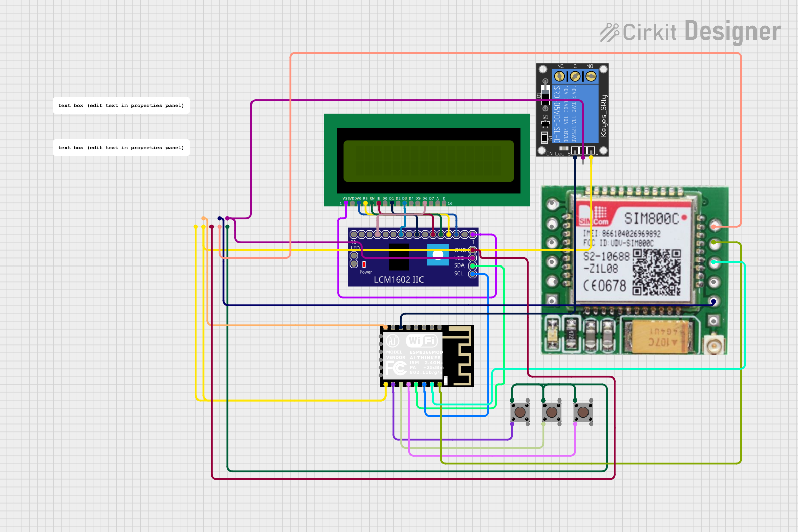
  • Arduino Compatibility: The Sigcom Pull can be used with Arduino boards to stabilize GPIO pins. Below is an example of using the Sigcom Pull with an Arduino UNO.

Example Code for Arduino UNO

// Example: Using Sigcom Pull (SG-42SK) as a pull-up resistor with Arduino UNO

const int buttonPin = 2;  // Pin connected to the button
const int ledPin = 13;    // Pin connected to the onboard LED

void setup() {
  pinMode(buttonPin, INPUT);  // Set button pin as input
  pinMode(ledPin, OUTPUT);    // Set LED pin as output
  digitalWrite(buttonPin, HIGH); // Enable internal pull-up resistor
}

void loop() {
  int buttonState = digitalRead(buttonPin); // Read the button state

  if (buttonState == LOW) {
    // Button is pressed (logic LOW due to pull-up configuration)
    digitalWrite(ledPin, HIGH); // Turn on the LED
  } else {
    // Button is not pressed
    digitalWrite(ledPin, LOW);  // Turn off the LED
  }
}

Troubleshooting and FAQs

Common Issues and Solutions

  1. Signal Line Still Floating:

    • Cause: Incorrect resistance value or improper connection.
    • Solution: Verify the resistance value and ensure the Sigcom Pull is securely connected to the signal line and VCC/GND.
  2. Excessive Power Dissipation:

    • Cause: Resistance value too low, causing high current flow.
    • Solution: Use a higher resistance value to limit current.
  3. Component Overheating:

    • Cause: Voltage or power rating exceeded.
    • Solution: Ensure the voltage across the Sigcom Pull does not exceed 50 V and the power dissipation stays below 0.25 W.
  4. Noise in Signal Line:

    • Cause: High-frequency noise or insufficient decoupling.
    • Solution: Add decoupling capacitors near the signal line to filter out noise.

FAQs

Q1: Can the Sigcom Pull (SG-42SK) be used with 3.3 V systems?
A1: Yes, the Sigcom Pull is compatible with 3.3 V systems as long as the resistance value is chosen appropriately.

Q2: What is the recommended resistance value for I2C pull-up resistors?
A2: For I2C communication, 4.7 kΩ or 10 kΩ is commonly used, depending on the bus speed and capacitance.

Q3: Can I use the Sigcom Pull in high-frequency circuits?
A3: Yes, but it is recommended to use decoupling capacitors to minimize noise and ensure signal integrity.

Q4: Is the Sigcom Pull available in surface-mount packages?
A4: Yes, the SG-42SK is available in both through-hole and surface-mount (SMD) packages for different design requirements.