Cirkit Designer Logo
Cirkit Designer
Your all-in-one circuit design IDE
Home / 
Component Documentation

How to Use Flora GPS: Examples, Pinouts, and Specs

Image of Flora GPS
Cirkit Designer LogoDesign with Flora GPS in Cirkit Designer

Introduction

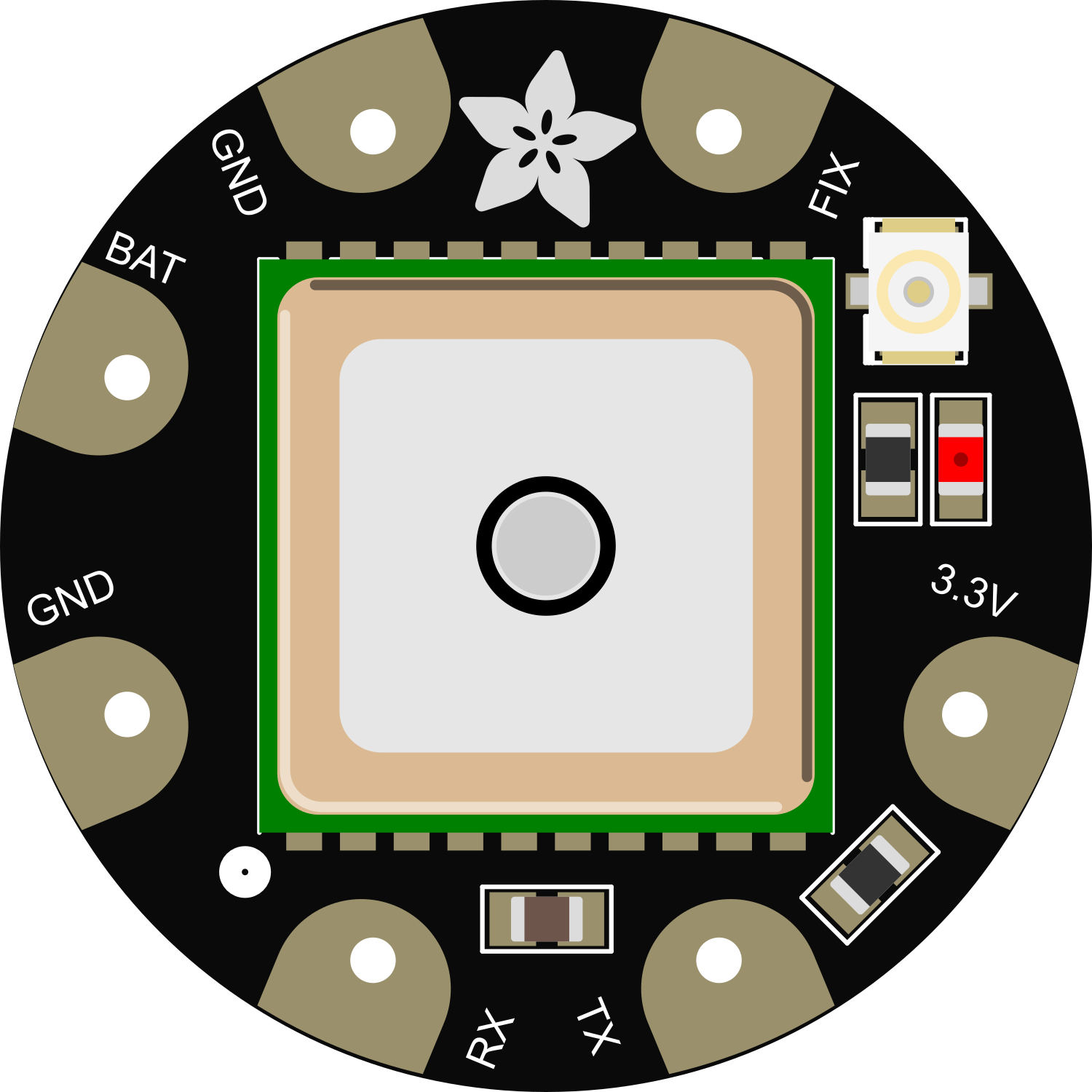
The Flora GPS module is a compact, high-performance GPS receiver designed for seamless integration with the Adafruit Flora platform, a wearable electronics platform. This module is based on the u-blox GPS chipset and is capable of providing precise timing and positional data. It is ideal for location-based projects, wearable devices, and any application where small size and accurate GPS tracking are essential.

Explore Projects Built with Flora GPS

Use Cirkit Designer to design, explore, and prototype these projects online. Some projects support real-time simulation. Click "Open Project" to start designing instantly!
Raspberry Pi 3B and Flora GPS-Based Real-Time Location Tracker
Image of prototype circuit: A project utilizing Flora GPS in a practical application
This circuit connects a Flora GPS module to a Raspberry Pi 3B. The GPS module is powered by the Raspberry Pi's 3.3V and GND pins, and communicates with the Raspberry Pi via UART using the TX and RX pins.
Cirkit Designer LogoOpen Project in Cirkit Designer
Battery-Powered Adafruit Flora RGB NeoPixel Light Show
Image of FloraTest: A project utilizing Flora GPS in a practical application
This circuit consists of an Adafruit Flora v3 microcontroller connected to a Breadboard-friendly RGB Smart NeoPixel and powered by a 3xAAA battery pack. The microcontroller runs code to control the NeoPixel, displaying various colors and patterns.
Cirkit Designer LogoOpen Project in Cirkit Designer
Arduino UNO with A9G GSM/GPRS and Dual VL53L1X Distance Sensors
Image of TED CIRCUIT : A project utilizing Flora GPS in a practical application
This circuit features an Arduino UNO microcontroller interfaced with an A9G GSM/GPRS+GPS/BDS module and two VL53L1X time-of-flight distance sensors. The A9G module is connected to the Arduino via serial communication for GPS and GSM functionalities, while both VL53L1X sensors are connected through I2C with shared SDA and SCL lines and individual SHUT pins for selective sensor activation. The Arduino is programmed to control these peripherals, although the specific functionality is not detailed in the provided code.
Cirkit Designer LogoOpen Project in Cirkit Designer
ESP32-Based GPS Tracker with OLED Display and Telegram Integration
Image of Yoon: A project utilizing Flora GPS in a practical application
This circuit is a GPS-based tracking system that uses an ESP32 microcontroller to receive GPS data from a NEO 6M module and display the coordinates on a 1.3" OLED screen. It also features WiFi connectivity to send location updates to a remote server, potentially for applications such as asset tracking or navigation assistance.
Cirkit Designer LogoOpen Project in Cirkit Designer

Explore Projects Built with Flora GPS

Use Cirkit Designer to design, explore, and prototype these projects online. Some projects support real-time simulation. Click "Open Project" to start designing instantly!
Image of prototype circuit: A project utilizing Flora GPS in a practical application
Raspberry Pi 3B and Flora GPS-Based Real-Time Location Tracker
This circuit connects a Flora GPS module to a Raspberry Pi 3B. The GPS module is powered by the Raspberry Pi's 3.3V and GND pins, and communicates with the Raspberry Pi via UART using the TX and RX pins.
Cirkit Designer LogoOpen Project in Cirkit Designer
Image of FloraTest: A project utilizing Flora GPS in a practical application
Battery-Powered Adafruit Flora RGB NeoPixel Light Show
This circuit consists of an Adafruit Flora v3 microcontroller connected to a Breadboard-friendly RGB Smart NeoPixel and powered by a 3xAAA battery pack. The microcontroller runs code to control the NeoPixel, displaying various colors and patterns.
Cirkit Designer LogoOpen Project in Cirkit Designer
Image of TED CIRCUIT : A project utilizing Flora GPS in a practical application
Arduino UNO with A9G GSM/GPRS and Dual VL53L1X Distance Sensors
This circuit features an Arduino UNO microcontroller interfaced with an A9G GSM/GPRS+GPS/BDS module and two VL53L1X time-of-flight distance sensors. The A9G module is connected to the Arduino via serial communication for GPS and GSM functionalities, while both VL53L1X sensors are connected through I2C with shared SDA and SCL lines and individual SHUT pins for selective sensor activation. The Arduino is programmed to control these peripherals, although the specific functionality is not detailed in the provided code.
Cirkit Designer LogoOpen Project in Cirkit Designer
Image of Yoon: A project utilizing Flora GPS in a practical application
ESP32-Based GPS Tracker with OLED Display and Telegram Integration
This circuit is a GPS-based tracking system that uses an ESP32 microcontroller to receive GPS data from a NEO 6M module and display the coordinates on a 1.3" OLED screen. It also features WiFi connectivity to send location updates to a remote server, potentially for applications such as asset tracking or navigation assistance.
Cirkit Designer LogoOpen Project in Cirkit Designer

Common Applications and Use Cases

  • Wearable GPS trackers
  • Location-based interactive projects
  • Data logging and mapping
  • Time synchronization for events

Technical Specifications

Key Technical Details

  • Chipset: u-blox GPS
  • Update Rate: Up to 10 Hz
  • Sensitivity: -160 dBm tracking, -148 dBm cold starts
  • Accuracy: 2.5 meters (GPS), 2 meters (SBAS)
  • Antenna: Built-in ceramic antenna
  • Interface: I2C and UART serial
  • Voltage: 3.3V to 5V supply input
  • Current: 20mA average tracking current

Pin Configuration and Descriptions

Pin Number Name Description
1 GND Ground connection
2 VIN Voltage input (3.3V to 5V)
3 RX UART Receive pin
4 TX UART Transmit pin
5 SCL I2C Clock pin
6 SDA I2C Data pin

Usage Instructions

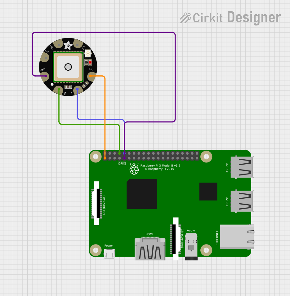
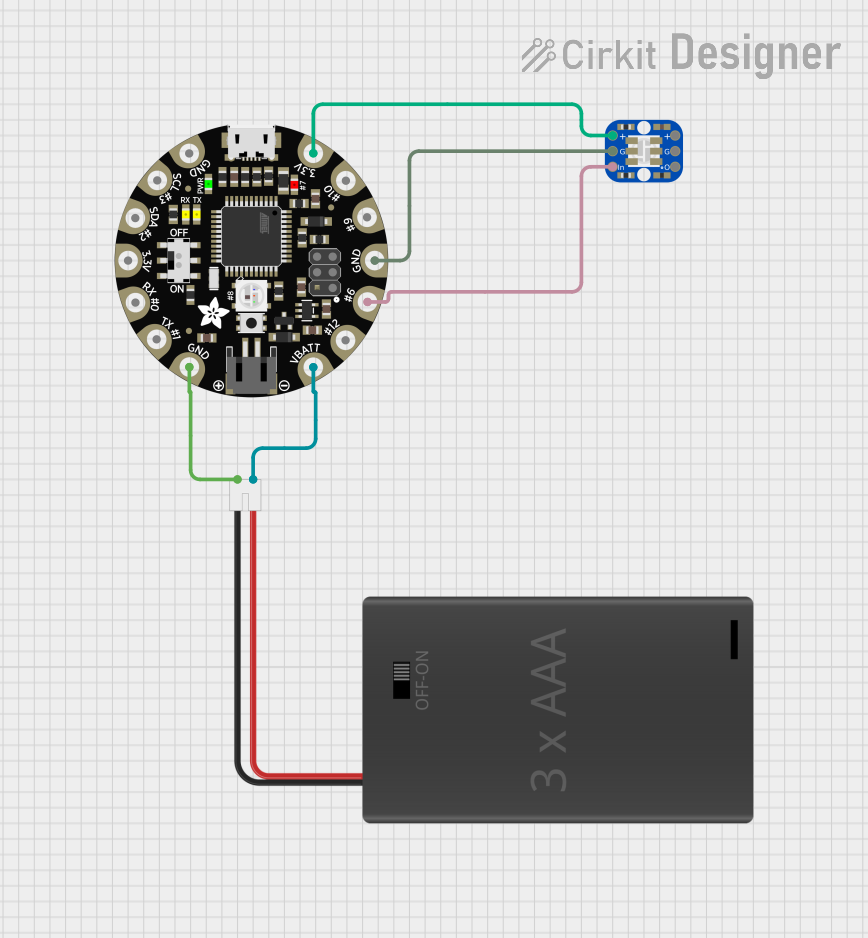
Integration with a Circuit

To use the Flora GPS module with the Adafruit Flora board:

  1. Connect the VIN pin of the GPS module to a 3.3V or 5V power supply.
  2. Connect the GND pin to the ground on the Flora board.
  3. For UART communication, connect the RX pin of the GPS module to the TX pin on the Flora, and the TX pin to the RX pin on the Flora.
  4. For I2C communication, connect the SCL and SDA pins to the corresponding I2C pins on the Flora board.

Important Considerations and Best Practices

  • Ensure that the GPS module has a clear view of the sky for optimal performance.
  • Avoid placing the module near devices that emit RF noise, as this can interfere with GPS signals.
  • When using I2C, remember to include pull-up resistors if they are not already present on the Flora board.

Example Code for Arduino UNO

#include <SoftwareSerial.h>
#include <TinyGPS++.h>

// Define the RX and TX pins connected to the Flora GPS module
#define GPS_RX_PIN 4
#define GPS_TX_PIN 3

// Set up the software serial port
SoftwareSerial gpsSerial(GPS_RX_PIN, GPS_TX_PIN);
TinyGPSPlus gps;

void setup() {
  // Start the serial communication with the host computer
  Serial.begin(9600);
  // Start the GPS communication
  gpsSerial.begin(9600);
  Serial.println("GPS Module Test");
}

void loop() {
  // Check for new GPS data and parse it
  while (gpsSerial.available() > 0) {
    if (gps.encode(gpsSerial.read())) {
      if (gps.location.isUpdated()) {
        // Print the location if it's updated
        Serial.print("Latitude: ");
        Serial.println(gps.location.lat(), 6);
        Serial.print("Longitude: ");
        Serial.println(gps.location.lng(), 6);
      }
    }
  }
}

Troubleshooting and FAQs

Common Issues

  • No GPS Data: Ensure the module has a clear view of the sky and that the antenna is not obstructed.
  • Inaccurate Position: Wait a few minutes for the GPS to get a fix. Initial accuracy may be lower until a stable connection with satellites is established.
  • Intermittent Data: Check the wiring and solder joints for loose connections.

Solutions and Tips for Troubleshooting

  • Power Cycle: Turn off the power to the module and the Flora board, wait a few seconds, and then turn it back on.
  • Check Serial Connections: Ensure that the RX and TX pins are correctly connected and that the baud rate matches the GPS module's default rate.
  • Use External Antenna: If the built-in antenna's performance is insufficient, consider using an external antenna with a u.FL connector if the module supports it.

FAQs

Q: How long does it take for the Flora GPS to get a fix? A: It can take anywhere from 30 seconds to several minutes for the GPS to get a fix, depending on conditions.

Q: Can I use the Flora GPS indoors? A: GPS signals are significantly weaker indoors. It's recommended to use the module outdoors or near a window for better reception.

Q: What is the power consumption of the Flora GPS? A: The module typically consumes around 20mA during tracking. Power consumption may vary based on usage and satellite conditions.