How to Use Q.Bloxx A108: Examples, Pinouts, and Specs
Introduction
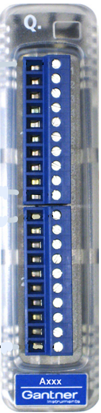
The Q.Bloxx A108 is a modular data acquisition and control system developed by Gantner Instruments. It is designed for educational and experimental purposes, offering a versatile platform for interfacing with a wide range of sensors and actuators. The system is ideal for prototyping, learning about electronics, and conducting experiments in fields such as automation, robotics, and IoT.
Explore Projects Built with Q.Bloxx A108

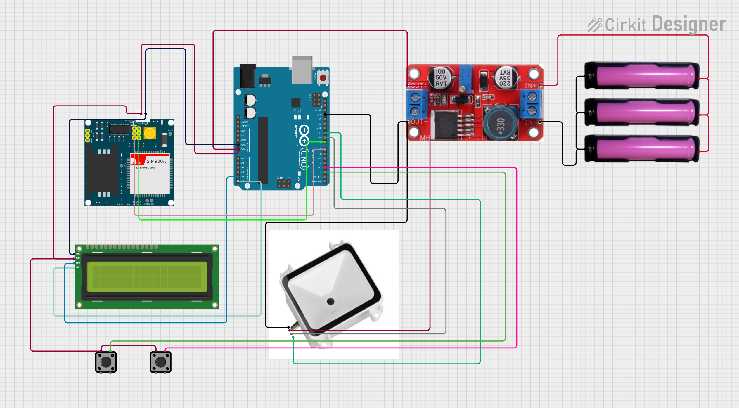

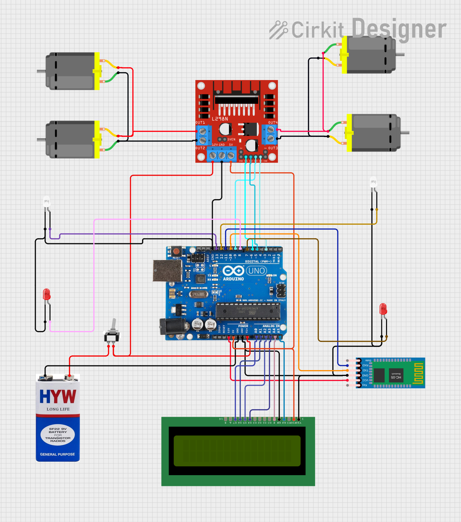
Explore Projects Built with Q.Bloxx A108
Common Applications and Use Cases
- Educational labs for teaching electronics and control systems
- Prototyping and testing of sensor-based systems
- Data acquisition in research and development projects
- Industrial automation and process control
- IoT applications requiring modular and scalable solutions
Technical Specifications
The Q.Bloxx A108 is equipped with robust features to support a variety of applications. Below are its key technical specifications:
General Specifications
| Parameter | Value |
|---|---|
| Manufacturer | Gantner Instruments |
| Part ID | Q.Bloxx A108 |
| Input Channels | 8 Analog Inputs |
| Output Channels | 4 Analog Outputs |
| Communication Interface | Ethernet, RS485 |
| Sampling Rate | Up to 100 kHz per channel |
| Power Supply | 10-30 V DC |
| Operating Temperature | -20°C to +60°C |
| Dimensions | 120 mm x 75 mm x 30 mm |
Pin Configuration and Descriptions
The Q.Bloxx A108 features a modular pin layout for connecting inputs, outputs, and communication interfaces. Below is the pin configuration:
Analog Input Pins
| Pin Number | Description | Signal Type |
|---|---|---|
| AI1 | Analog Input Channel 1 | Voltage/Current |
| AI2 | Analog Input Channel 2 | Voltage/Current |
| AI3 | Analog Input Channel 3 | Voltage/Current |
| AI4 | Analog Input Channel 4 | Voltage/Current |
| AI5 | Analog Input Channel 5 | Voltage/Current |
| AI6 | Analog Input Channel 6 | Voltage/Current |
| AI7 | Analog Input Channel 7 | Voltage/Current |
| AI8 | Analog Input Channel 8 | Voltage/Current |
Analog Output Pins
| Pin Number | Description | Signal Type |
|---|---|---|
| AO1 | Analog Output Channel 1 | Voltage/Current |
| AO2 | Analog Output Channel 2 | Voltage/Current |
| AO3 | Analog Output Channel 3 | Voltage/Current |
| AO4 | Analog Output Channel 4 | Voltage/Current |
Communication and Power Pins
| Pin Number | Description | Signal Type |
|---|---|---|
| COM+ | Communication Positive | RS485/Ethernet |
| COM- | Communication Negative | RS485/Ethernet |
| V+ | Power Supply Positive | 10-30 V DC |
| V- | Power Supply Negative | Ground |
Usage Instructions
The Q.Bloxx A108 is designed for ease of use in a variety of applications. Follow the steps below to integrate it into your project:
Step 1: Powering the Device
- Connect the V+ pin to a DC power supply (10-30 V DC).
- Connect the V- pin to the ground of the power supply.
- Ensure the power supply is stable and within the specified voltage range.
Step 2: Connecting Inputs and Outputs
- Connect your sensors to the AI1-AI8 pins for analog input signals.
- Ensure the sensors' output voltage or current is within the supported range.
- Connect your actuators or other devices to the AO1-AO4 pins for analog output signals.
- Verify the actuators' input requirements match the output specifications of the Q.Bloxx A108.
Step 3: Communication Setup
- For Ethernet communication:
- Connect the Ethernet cable to the communication interface.
- Configure the IP address and communication settings using the provided software.
- For RS485 communication:
- Connect the COM+ and COM- pins to the RS485 network.
- Set the baud rate and other parameters as required.
Step 4: Programming and Control
The Q.Bloxx A108 can be controlled using various programming platforms. Below is an example of interfacing it with an Arduino UNO for basic data acquisition:
// Example: Reading analog input from Q.Bloxx A108 using Arduino UNO
// Ensure proper wiring between Q.Bloxx A108 and Arduino UNO

#define ANALOG_PIN A0  // Connect Q.Bloxx A108 AI1 to Arduino A0

void setup() {
  Serial.begin(9600);  // Initialize serial communication
  pinMode(ANALOG_PIN, INPUT);  // Set A0 as input
}

void loop() {
  int sensorValue = analogRead(ANALOG_PIN);  // Read analog value
  float voltage = sensorValue * (5.0 / 1023.0);  // Convert to voltage
  Serial.print("Sensor Voltage: ");
  Serial.println(voltage);  // Print voltage to serial monitor
  delay(500);  // Wait for 500 ms
}
Best Practices
- Use shielded cables for analog signals to minimize noise.
- Ensure proper grounding to avoid ground loops.
- Regularly calibrate the device for accurate measurements.
- Use the manufacturer's software for advanced configuration and diagnostics.
Troubleshooting and FAQs
Common Issues and Solutions
Device not powering on:
- Verify the power supply voltage is within the 10-30 V DC range.
- Check the connections to the V+ and V- pins.
No communication with the device:
- Ensure the Ethernet or RS485 cables are securely connected.
- Verify the communication settings (e.g., IP address, baud rate).
Incorrect or unstable readings:
- Check the sensor connections and ensure they are secure.
- Use shielded cables to reduce noise interference.
- Verify the input signal is within the supported range.
Output not functioning:
- Confirm the actuator is properly connected to the output pins.
- Check the output configuration in the software.
FAQs
Q: Can the Q.Bloxx A108 be used with wireless communication?
A: The Q.Bloxx A108 does not have built-in wireless capabilities, but you can use an external wireless module (e.g., Wi-Fi or Bluetooth) connected to the communication interface.
Q: What is the maximum cable length for analog inputs?
A: The maximum cable length depends on the signal type and environment. For best results, use shielded cables and keep the length under 10 meters.
Q: Is the Q.Bloxx A108 compatible with LabVIEW?
A: Yes, the Q.Bloxx A108 is compatible with LabVIEW. Gantner Instruments provides drivers and libraries for integration.
Q: How do I update the firmware?
A: Firmware updates can be performed using the manufacturer's software. Follow the instructions provided in the user manual.
By following this documentation, users can effectively utilize the Q.Bloxx A108 for their data acquisition and control needs.