How to Use GPS Receiver Module: Examples, Pinouts, and Specs
Introduction
The Ruiqi GPS Receiver Module is a compact and efficient device designed to receive signals from GPS satellites and calculate precise location data, including latitude, longitude, altitude, and time. This module is widely used in navigation systems, vehicle tracking, geolocation-based applications, and IoT devices requiring real-time positioning.
With its high sensitivity and low power consumption, the Ruiqi GPS Receiver Module is ideal for both portable and embedded systems. It supports standard NMEA (National Marine Electronics Association) protocols, making it compatible with a wide range of microcontrollers and development platforms.
Explore Projects Built with GPS Receiver Module
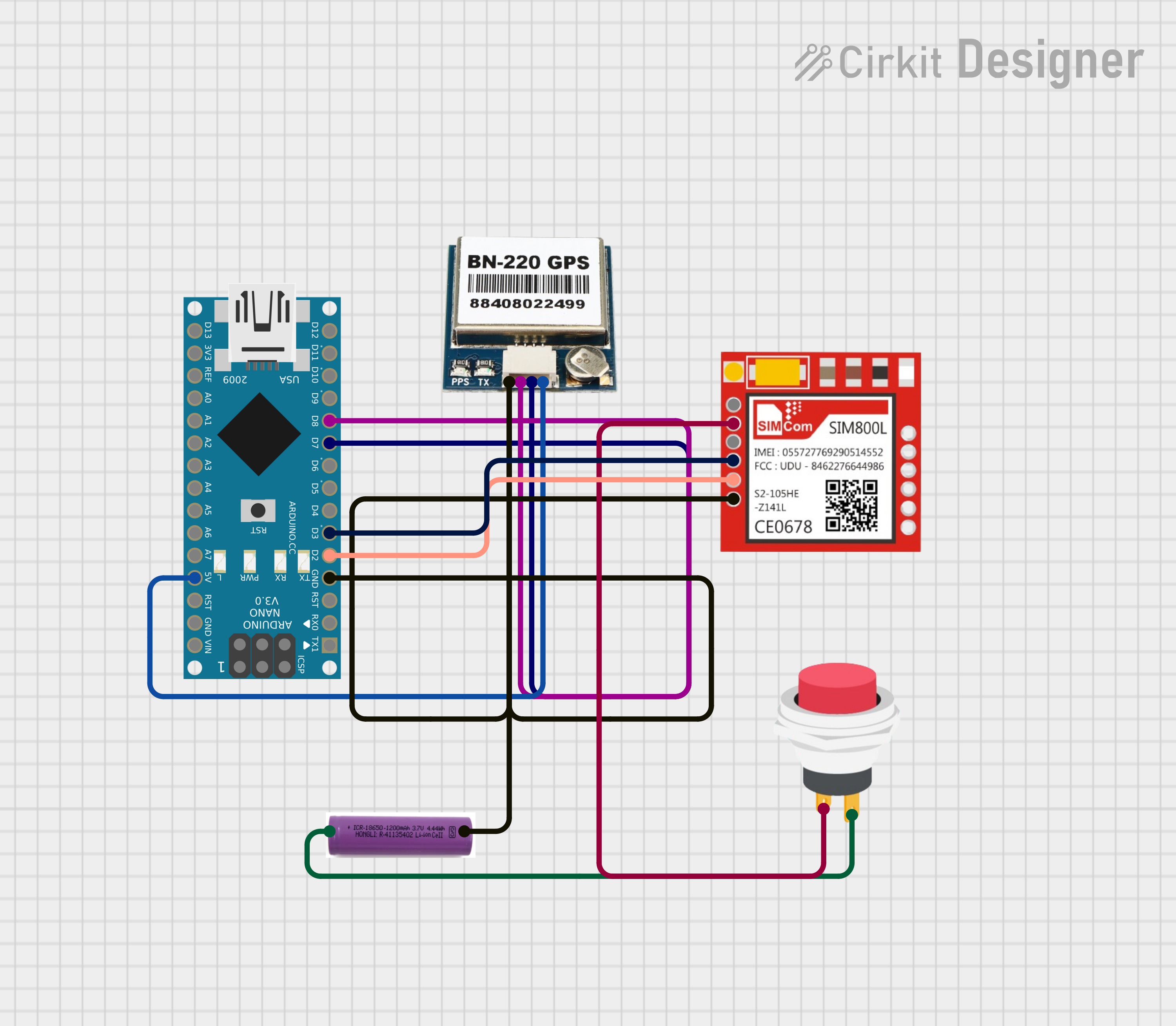
Explore Projects Built with GPS Receiver Module
Technical Specifications
Below are the key technical details of the Ruiqi GPS Receiver Module:
| Parameter | Specification |
|---|---|
| Operating Voltage | 3.3V to 5.0V |
| Operating Current | 20mA (typical) |
| Communication Interface | UART (TTL level) |
| Baud Rate | 9600 bps (default, configurable) |
| Positioning Accuracy | ±2.5 meters (open sky) |
| Cold Start Time | < 35 seconds |
| Hot Start Time | < 1 second |
| Protocol Support | NMEA 0183 (GGA, GLL, GSA, GSV, RMC) |
| Operating Temperature | -40°C to +85°C |
| Dimensions | 25mm x 25mm x 8mm |
Pin Configuration
The Ruiqi GPS Receiver Module has a simple pinout for easy integration into circuits:
| Pin | Name | Description |
|---|---|---|
| 1 | VCC | Power supply input (3.3V to 5.0V) |
| 2 | GND | Ground connection |
| 3 | TX | UART Transmit pin (sends GPS data to the host) |
| 4 | RX | UART Receive pin (receives configuration commands) |
| 5 | PPS | Pulse Per Second output (optional, for timing) |
Usage Instructions
How to Use the GPS Receiver Module in a Circuit
- Power Supply: Connect the
VCCpin to a 3.3V or 5.0V power source and theGNDpin to the ground of your circuit. - UART Communication: Connect the
TXpin of the module to theRXpin of your microcontroller (e.g., Arduino UNO) and theRXpin of the module to theTXpin of the microcontroller. - Antenna Placement: Ensure the module's antenna has a clear view of the sky for optimal satellite signal reception.
- Data Parsing: The module outputs NMEA sentences via the
TXpin. Use a microcontroller or software to parse these sentences and extract location data.
Important Considerations and Best Practices
- Antenna Orientation: Place the module in an open area with minimal obstructions for better GPS signal reception.
- Power Stability: Use a stable power supply to avoid disruptions in GPS data output.
- Baud Rate Configuration: The default baud rate is 9600 bps. If needed, configure the baud rate using appropriate commands sent via the
RXpin. - PPS Pin: The
PPSpin provides a precise timing pulse once per second, which can be used for time synchronization in advanced applications.
Example: Connecting to an Arduino UNO
Below is an example of how to interface the Ruiqi GPS Receiver Module with an Arduino UNO and read GPS data:
#include <SoftwareSerial.h>

// Define RX and TX pins for the GPS module
SoftwareSerial gpsSerial(4, 3); // RX = Pin 4, TX = Pin 3

void setup() {
  Serial.begin(9600);          // Initialize Serial Monitor at 9600 bps
  gpsSerial.begin(9600);       // Initialize GPS module at 9600 bps
  Serial.println("GPS Module Initialized");
}

void loop() {
  // Check if data is available from the GPS module
  while (gpsSerial.available()) {
    char c = gpsSerial.read(); // Read one character from the GPS module
    Serial.print(c);           // Print the character to the Serial Monitor
  }
}
Note: The above code reads raw NMEA sentences from the GPS module and displays them on the Serial Monitor. Use a GPS parsing library (e.g., TinyGPS++) to extract specific data like latitude and longitude.
Troubleshooting and FAQs
Common Issues and Solutions
No GPS Data Output:
- Cause: Poor satellite signal reception.
- Solution: Ensure the module's antenna has a clear view of the sky and is not obstructed by buildings or metal objects.
Incorrect or Inconsistent Location Data:
- Cause: Insufficient satellite connections.
- Solution: Wait for the module to establish a stable connection with at least 4 satellites.
Module Not Responding:
- Cause: Incorrect wiring or baud rate mismatch.
- Solution: Double-check the connections and ensure the baud rate is set to 9600 bps.
High Power Consumption:
- Cause: Continuous operation in high-sensitivity mode.
- Solution: Use power-saving modes if supported by the module.
FAQs
Q: Can the module work indoors?
- A: The module may work indoors near windows, but performance will be significantly reduced compared to outdoor use.
Q: How do I change the baud rate?
- A: Send the appropriate configuration command via the
RXpin. Refer to the module's command set for details.
- A: Send the appropriate configuration command via the
Q: What is the purpose of the PPS pin?
- A: The PPS pin provides a precise timing pulse for synchronization in time-sensitive applications.
By following this documentation, you can effectively integrate and use the Ruiqi GPS Receiver Module in your projects.