How to Use 8 Channel 5v Relay: Examples, Pinouts, and Specs
Introduction
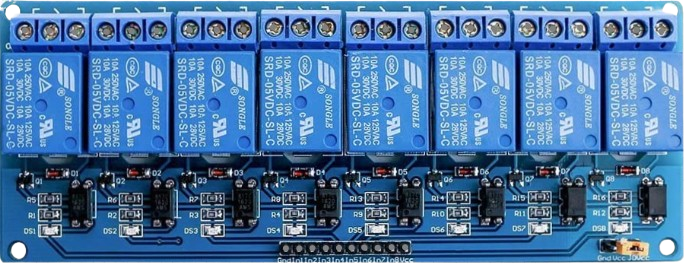
The 8 Channel 5V Relay (Manufacturer: AC, Part ID: Relay) is a versatile relay module designed to control multiple high-power devices using low-power control signals, typically from a microcontroller such as an Arduino. This module features 8 independent relays, allowing users to switch up to 8 devices simultaneously. It operates on a 5V power supply and is ideal for applications requiring electrical isolation and high-current switching.
Explore Projects Built with 8 Channel 5v Relay


Explore Projects Built with 8 Channel 5v Relay
Common Applications
- Home automation (e.g., controlling lights, fans, or appliances)
- Industrial automation and control systems
- Robotics and motor control
- IoT (Internet of Things) projects
- Security systems (e.g., activating alarms or locks)
Technical Specifications
Below are the key technical details of the 8 Channel 5V Relay module:
| Parameter | Specification |
|---|---|
| Operating Voltage | 5V DC |
| Trigger Voltage | 3.3V to 5V DC |
| Relay Type | Electromechanical |
| Number of Channels | 8 |
| Maximum Load (AC) | 250V AC at 10A |
| Maximum Load (DC) | 30V DC at 10A |
| Isolation | Optocoupler isolation for each relay |
| Dimensions | ~140mm x 50mm x 20mm |
| Weight | ~120g |
Pin Configuration and Descriptions
The module has two main sections: the control pins and the relay output terminals.
Control Pins
| Pin Name | Description |
|---|---|
| VCC | Connect to 5V power supply. |
| GND | Connect to ground. |
| IN1 to IN8 | Control pins for each relay channel. A LOW signal activates the corresponding relay. |
Relay Output Terminals
Each relay has three output terminals:
| Terminal | Description |
|---|---|
| NO (Normally Open) | Open circuit when the relay is inactive. Closes when the relay is activated. |
| NC (Normally Closed) | Closed circuit when the relay is inactive. Opens when the relay is activated. |
| COM (Common) | Common terminal for the relay. Connect the load to this terminal. |
Usage Instructions
How to Use the 8 Channel 5V Relay in a Circuit
- Power the Module: Connect the VCC pin to a 5V power supply and the GND pin to ground.
- Connect the Control Signals: Use a microcontroller (e.g., Arduino) to send control signals to the IN1 to IN8 pins. A LOW signal activates the corresponding relay.
- Connect the Load: For each relay, connect the load to the NO or NC terminal and the COM terminal, depending on whether you want the load to be normally off or on.
- Test the Circuit: Ensure all connections are secure and test the circuit by toggling the control signals.
Important Considerations and Best Practices
- Power Supply: Ensure the module is powered with a stable 5V DC supply. Avoid exceeding the voltage rating.
- Isolation: The module features optocoupler isolation, which protects the control circuit from high voltages. However, ensure proper grounding to avoid electrical noise.
- Load Ratings: Do not exceed the maximum load ratings (250V AC at 10A or 30V DC at 10A) to prevent damage to the relays.
- Inductive Loads: When switching inductive loads (e.g., motors), use a flyback diode across the load to suppress voltage spikes.
Example: Connecting to an Arduino UNO
Below is an example of how to control the 8 Channel 5V Relay module using an Arduino UNO:
Circuit Connections
- Connect the relay module's VCC to the Arduino's 5V pin.
- Connect the relay module's GND to the Arduino's GND pin.
- Connect the IN1 to IN8 pins to digital pins 2 to 9 on the Arduino.
Arduino Code
// Example code to control an 8 Channel 5V Relay module with Arduino UNO

// Define the relay control pins
const int relayPins[] = {2, 3, 4, 5, 6, 7, 8, 9};

void setup() {
  // Initialize all relay pins as OUTPUT
  for (int i = 0; i < 8; i++) {
    pinMode(relayPins[i], OUTPUT);
    digitalWrite(relayPins[i], HIGH); // Set all relays to OFF state
  }
}

void loop() {
  // Example: Sequentially turn on each relay for 1 second
  for (int i = 0; i < 8; i++) {
    digitalWrite(relayPins[i], LOW);  // Activate relay (LOW signal)
    delay(1000);                      // Wait for 1 second
    digitalWrite(relayPins[i], HIGH); // Deactivate relay (HIGH signal)
  }
}
Troubleshooting and FAQs
Common Issues and Solutions
Relays Not Activating
- Cause: Insufficient power supply.
- Solution: Ensure the module is powered with a stable 5V DC supply.
Microcontroller Cannot Trigger Relays
- Cause: Control signal voltage is too low.
- Solution: Verify that the control signal voltage is between 3.3V and 5V.
Load Not Switching Properly
- Cause: Incorrect wiring of the load to the relay terminals.
- Solution: Double-check the connections to the NO, NC, and COM terminals.
Relay Module Overheating
- Cause: Exceeding the maximum load ratings.
- Solution: Ensure the load does not exceed 250V AC at 10A or 30V DC at 10A.
FAQs
Q: Can I use this module with a 3.3V microcontroller like the ESP8266?
A: Yes, the module can be triggered with 3.3V control signals. However, ensure the VCC pin is still powered with 5V.
Q: Is it safe to use this module for high-power appliances?
A: Yes, as long as the load does not exceed the maximum ratings. For added safety, use proper fuses and circuit breakers.
Q: Can I control DC motors with this relay module?
A: Yes, but for inductive loads like motors, use a flyback diode to protect the relay from voltage spikes.
Q: What happens if I connect the relays incorrectly?
A: Incorrect wiring may result in the load not switching or potential damage to the module. Always double-check connections before powering the circuit.