How to Use Lilypad accelerometer: Examples, Pinouts, and Specs
Introduction
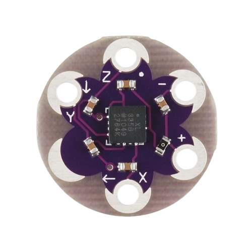
The LilyPad Accelerometer - ADXL335 is a compact, lightweight sensor designed by SparkFun for wearable electronics and e-textile projects. It measures acceleration forces in three dimensions (X, Y, and Z axes), making it ideal for detecting motion, orientation, and tilt. Its circular design and sewable pads make it easy to integrate into fabric-based projects.
Explore Projects Built with Lilypad accelerometer
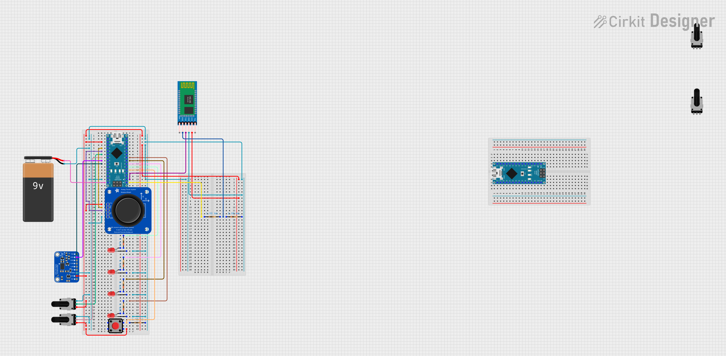

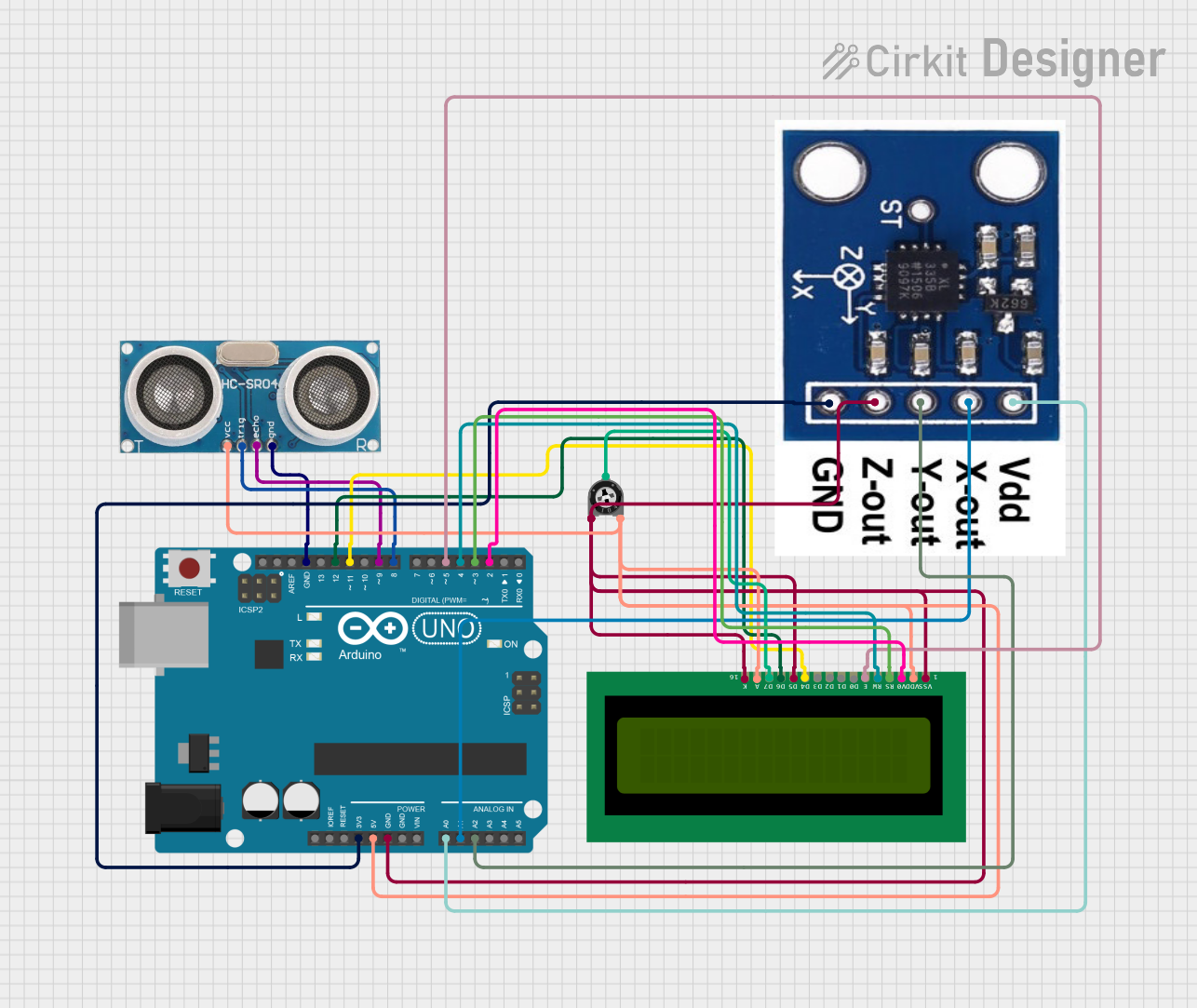
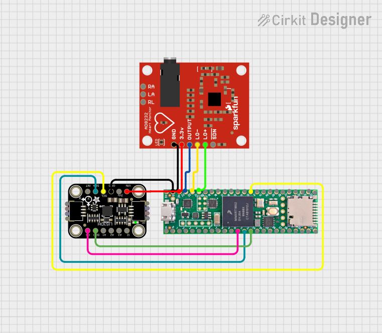
Explore Projects Built with Lilypad accelerometer
Common Applications
- Motion detection in wearable devices
- Orientation tracking for interactive garments
- Gesture-based controls
- Fitness and activity monitoring
- Robotics and gaming projects
Technical Specifications
The LilyPad Accelerometer is based on the Analog Devices ADXL335 sensor. Below are its key technical details:
| Parameter | Value |
|---|---|
| Operating Voltage | 1.8V to 3.6V (3.3V recommended) |
| Operating Current | 350 µA |
| Measurement Range | ±3g |
| Sensitivity | 300 mV/g (typical at 3.3V) |
| Output Type | Analog |
| Dimensions | 20mm diameter |
| Weight | ~1g |
Pin Configuration and Descriptions
The LilyPad Accelerometer has six sewable connection pads. Below is the pinout:
| Pin Name | Description |
|---|---|
+ |
Power supply input (3.3V recommended) |
- |
Ground connection |
X |
Analog output for X-axis acceleration |
Y |
Analog output for Y-axis acceleration |
Z |
Analog output for Z-axis acceleration |
ST |
Self-test pin (used for testing the sensor; leave unconnected for normal use) |
Usage Instructions
How to Use the LilyPad Accelerometer in a Circuit
- Power the Sensor: Connect the
+pad to a 3.3V power source and the-pad to ground. - Read the Outputs: Connect the
X,Y, andZpads to analog input pins on your microcontroller (e.g., Arduino UNO). - Process the Data: The sensor outputs an analog voltage proportional to the acceleration along each axis. Use an ADC (Analog-to-Digital Converter) to read and process these values.
Important Considerations and Best Practices
- Voltage Levels: Ensure the power supply voltage does not exceed 3.6V to avoid damaging the sensor.
- Calibration: For accurate measurements, calibrate the sensor by determining the zero-g offset for each axis.
- Mounting: Secure the sensor firmly to minimize noise caused by vibrations.
- Filtering: Use software filtering techniques to smooth out noisy readings, especially in dynamic environments.
Example: Connecting to an Arduino UNO
Below is an example of how to connect and read data from the LilyPad Accelerometer using an Arduino UNO:
Circuit Connections
- Connect the
+pad to the Arduino's3.3Vpin. - Connect the
-pad to the Arduino'sGNDpin. - Connect the
X,Y, andZpads to the Arduino'sA0,A1, andA2pins, respectively.
Arduino Code
// LilyPad Accelerometer - ADXL335 Example Code
// Reads acceleration data from the X, Y, and Z axes and prints it to the Serial Monitor.

const int xPin = A0; // X-axis connected to analog pin A0
const int yPin = A1; // Y-axis connected to analog pin A1
const int zPin = A2; // Z-axis connected to analog pin A2

void setup() {
  Serial.begin(9600); // Initialize serial communication at 9600 baud
}

void loop() {
  // Read analog values from the accelerometer
  int xValue = analogRead(xPin);
  int yValue = analogRead(yPin);
  int zValue = analogRead(zPin);

  // Print the raw values to the Serial Monitor
  Serial.print("X: ");
  Serial.print(xValue);
  Serial.print(" | Y: ");
  Serial.print(yValue);
  Serial.print(" | Z: ");
  Serial.println(zValue);

  delay(500); // Wait for 500ms before the next reading
}
Interpreting the Output
- The raw analog values range from 0 to 1023 (10-bit ADC resolution).
- At 0g (no acceleration), the output voltage is approximately half the supply voltage (e.g., ~1.65V for a 3.3V supply).
- Use the sensor's sensitivity (300 mV/g) to convert the voltage readings into acceleration values in g.
Troubleshooting and FAQs
Common Issues and Solutions
No Output or Incorrect Readings
- Cause: Incorrect wiring or insufficient power supply.
- Solution: Double-check all connections and ensure the sensor is powered with 3.3V.
Noisy or Fluctuating Readings
- Cause: External vibrations or electrical noise.
- Solution: Secure the sensor firmly and use software filtering (e.g., averaging or low-pass filters).
Readings Drift Over Time
- Cause: Temperature changes affecting the sensor.
- Solution: Periodically recalibrate the sensor to account for drift.
Self-Test Pin Confusion
- Cause: Misuse of the
STpin. - Solution: Leave the
STpin unconnected during normal operation.
- Cause: Misuse of the
FAQs
Q: Can I use the LilyPad Accelerometer with a 5V microcontroller?
A: Yes, but you must use a voltage regulator or level shifter to step down the 5V to 3.3V for the sensor.
Q: How do I calibrate the sensor?
A: Measure the output voltage for each axis when the sensor is stationary and level. Use these values as the zero-g offsets in your calculations.
Q: Can the sensor detect free fall?
A: Yes, during free fall, all three axes will measure approximately 0g.
Q: Is the sensor waterproof?
A: No, the LilyPad Accelerometer is not waterproof. Protect it from moisture when used in wearable projects.