How to Use AS7341: Examples, Pinouts, and Specs
Introduction
The AS7341 is a highly advanced spectral sensor manufactured by AMS. It is designed to measure light intensity across multiple wavelengths, making it ideal for applications requiring precise color and light analysis. The sensor features 11 channels for color sensing, enabling accurate detection of visible and near-infrared light. Its compact design and high sensitivity make it suitable for a wide range of applications, including color recognition, ambient light sensing, and environmental monitoring.
Explore Projects Built with AS7341


Explore Projects Built with AS7341
Common Applications
- Color recognition in industrial and consumer devices
- Ambient light sensing for display brightness adjustment
- Environmental monitoring and light quality analysis
- Agricultural and horticultural applications for light spectrum analysis
- Scientific research and laboratory equipment
Technical Specifications
The AS7341 is a versatile sensor with the following key technical details:
| Parameter | Value |
|---|---|
| Manufacturer | AMS |
| Part Number | AS7341 |
| Spectral Channels | 11 (visible and near-infrared) |
| Supply Voltage (VDD) | 1.8V |
| I²C Interface Voltage (VDDIO) | 1.8V to 3.3V |
| Operating Current | 190 µA (typical) |
| Spectral Range | 350 nm to 1000 nm |
| Communication Interface | I²C (up to 1 MHz) |
| Package Type | LGA (2.0 mm x 2.0 mm x 0.5 mm) |
| Operating Temperature Range | -40°C to +85°C |
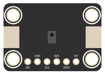
Pin Configuration and Descriptions
The AS7341 has 8 pins, as described in the table below:
| Pin | Name | Type | Description |
|---|---|---|---|
| 1 | VDD | Power | Main power supply (1.8V). |
| 2 | VDDIO | Power | I²C interface power supply (1.8V to 3.3V). |
| 3 | GND | Ground | Ground connection. |
| 4 | SDA | I²C Data | Serial data line for I²C communication. |
| 5 | SCL | I²C Clock | Serial clock line for I²C communication. |
| 6 | INT | Output | Interrupt output (active low). |
| 7 | GPIO | Input/Output | General-purpose input/output pin. |
| 8 | NC | Not Connected | No internal connection; leave unconnected. |
Usage Instructions
How to Use the AS7341 in a Circuit
- Power Supply: Connect the VDD pin to a 1.8V power source and the VDDIO pin to a 1.8V to 3.3V source, depending on your I²C voltage level.
- I²C Communication: Connect the SDA and SCL pins to the corresponding data and clock lines of your microcontroller. Use pull-up resistors (typically 4.7 kΩ) on both lines.
- Interrupt Pin: Optionally, connect the INT pin to a GPIO pin on your microcontroller to handle interrupts.
- Ground Connection: Connect the GND pin to the ground of your circuit.
- Initialization: Configure the AS7341 using I²C commands to set up the desired measurement mode and spectral channels.
Important Considerations
- Ensure the power supply voltage levels are within the specified range to avoid damaging the sensor.
- Use proper pull-up resistors on the I²C lines for reliable communication.
- Avoid exposing the sensor to extreme temperatures or humidity levels beyond its operating range.
- Place the sensor in a location where it can receive unobstructed light for accurate measurements.
Example Code for Arduino UNO
Below is an example of how to interface the AS7341 with an Arduino UNO using the Wire library:
#include <Wire.h>

#define AS7341_I2C_ADDR 0x39 // Default I²C address of AS7341

void setup() {
  Wire.begin(); // Initialize I²C communication
  Serial.begin(9600); // Initialize serial communication for debugging

  // Initialize the AS7341
  if (!initializeAS7341()) {
    Serial.println("AS7341 initialization failed!");
    while (1); // Halt execution if initialization fails
  }
  Serial.println("AS7341 initialized successfully!");
}

void loop() {
  // Read and print light intensity data
  uint16_t channelData = readChannelData(0x95); // Example: Read channel F1
  Serial.print("Channel F1 Intensity: ");
  Serial.println(channelData);

  delay(1000); // Wait 1 second before the next reading
}

bool initializeAS7341() {
  Wire.beginTransmission(AS7341_I2C_ADDR);
  Wire.write(0x80); // Enable register
  Wire.write(0x01); // Power ON the sensor
  if (Wire.endTransmission() != 0) {
    return false; // Return false if communication fails
  }
  return true;
}

uint16_t readChannelData(uint8_t channelRegister) {
  Wire.beginTransmission(AS7341_I2C_ADDR);
  Wire.write(channelRegister); // Specify the channel register to read
  if (Wire.endTransmission(false) != 0) {
    return 0; // Return 0 if communication fails
  }

  Wire.requestFrom(AS7341_I2C_ADDR, 2); // Request 2 bytes of data
  if (Wire.available() < 2) {
    return 0; // Return 0 if data is not available
  }

  uint16_t data = Wire.read(); // Read the first byte
  data |= (Wire.read() << 8);  // Read the second byte and combine
  return data;
}
Notes on the Code
- The
initializeAS7341()function powers on the sensor by writing to the enable register. - The
readChannelData()function reads the intensity data from a specified channel register. - Replace
0x95in thereadChannelData()function with the register address of the desired channel.
Troubleshooting and FAQs
Common Issues
No Response from the Sensor
- Ensure the I²C address (default: 0x39) matches the one used in your code.
- Verify the pull-up resistors on the SDA and SCL lines are correctly connected.
- Check the power supply voltage levels for VDD and VDDIO.
Incorrect or Inconsistent Readings
- Ensure the sensor is not obstructed and is exposed to the light source.
- Verify the initialization sequence and configuration settings.
- Avoid electrical noise or interference on the I²C lines.
Interrupt Pin Not Functioning
- Ensure the INT pin is connected to a GPIO pin on your microcontroller.
- Verify the interrupt configuration in the AS7341 registers.
Tips for Troubleshooting
- Use an I²C scanner sketch to confirm the sensor's address.
- Check all connections with a multimeter to ensure proper continuity.
- Refer to the AS7341 datasheet for detailed register descriptions and configuration options.
By following this documentation, you can effectively integrate the AS7341 spectral sensor into your projects and achieve accurate light and color measurements.