How to Use SUPMEA: Examples, Pinouts, and Specs
Introduction
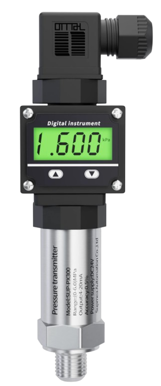
The SUPMEA is a precision measurement device designed for use in electronic circuits to measure voltage, current, and resistance with high accuracy. Manufactured by SUPMEA, this component is ideal for applications requiring precise monitoring and control of electrical parameters. Its robust design and high accuracy make it suitable for use in laboratory equipment, industrial automation, and educational projects.
Explore Projects Built with SUPMEA

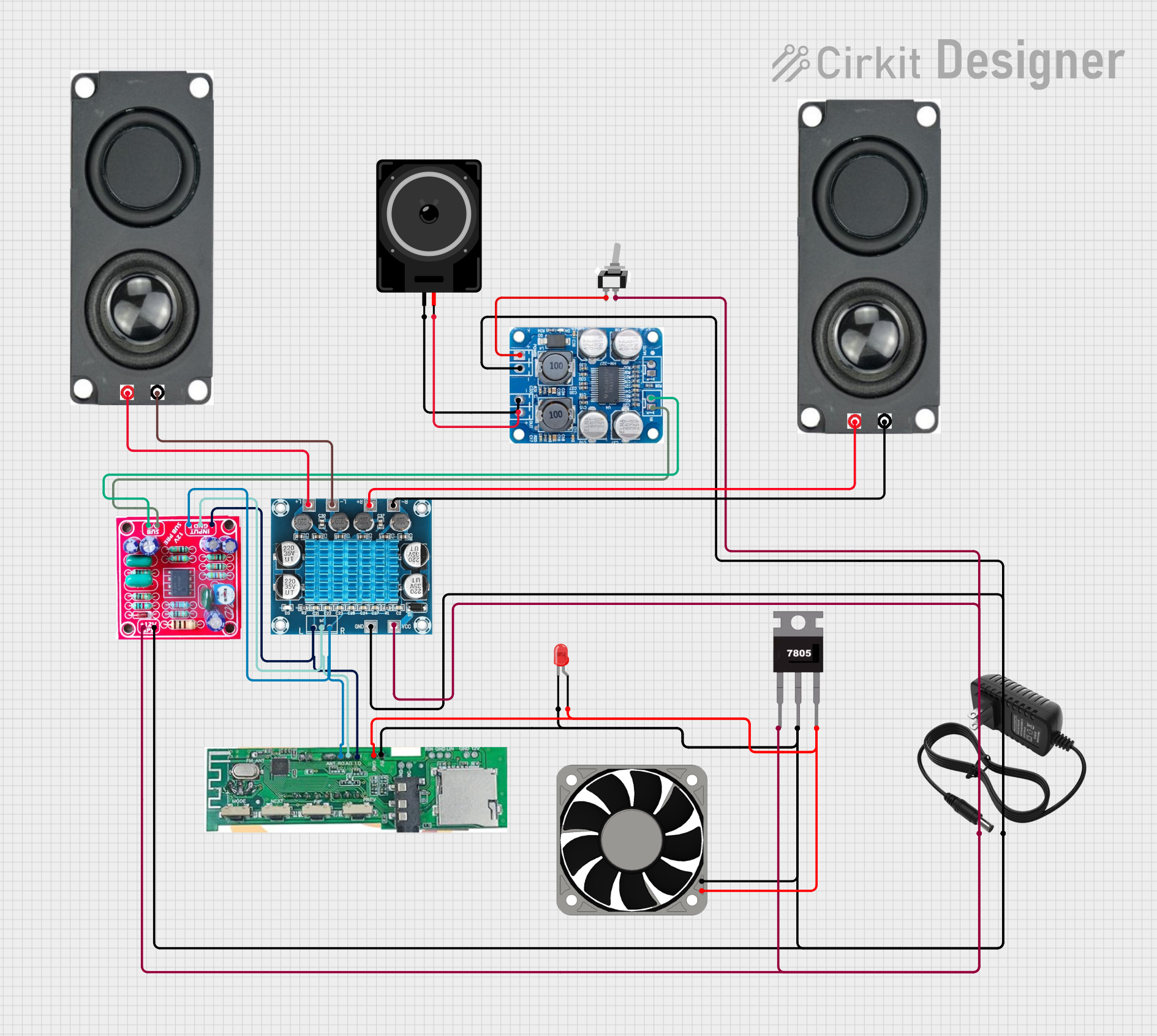


Explore Projects Built with SUPMEA
Common Applications and Use Cases
- Voltage, current, and resistance measurement in electronic circuits
- Industrial process monitoring and control
- Laboratory testing and calibration equipment
- Educational and prototyping projects
- Integration with microcontroller platforms like Arduino for data acquisition
Technical Specifications
The SUPMEA is engineered to deliver reliable and accurate measurements. Below are its key technical specifications:
| Parameter | Value |
|---|---|
| Operating Voltage | 5V DC |
| Measurement Range | Voltage: 0-30V, Current: 0-5A, Resistance: 0-10MΩ |
| Accuracy | ±0.1% |
| Input Impedance | 10MΩ (voltage measurement) |
| Operating Temperature | -10°C to 50°C |
| Communication Interface | Analog output or UART (optional) |
| Dimensions | 50mm x 30mm x 10mm |
Pin Configuration and Descriptions
The SUPMEA has a simple pinout for easy integration into circuits. Below is the pin configuration:
| Pin | Name | Description |
|---|---|---|
| 1 | VCC | Power supply input (5V DC) |
| 2 | GND | Ground connection |
| 3 | V_OUT | Analog voltage output proportional to the measured value |
| 4 | UART_TX (opt.) | UART transmit pin for digital communication (optional) |
| 5 | UART_RX (opt.) | UART receive pin for digital communication (optional) |
Usage Instructions
The SUPMEA is straightforward to use in a circuit. Follow the steps below to integrate and operate the component:
- Power Supply: Connect the VCC pin to a 5V DC power source and the GND pin to the ground of your circuit.
- Measurement Setup:
- For voltage measurement, connect the input terminals to the voltage source to be measured.
- For current measurement, place the SUPMEA in series with the load.
- For resistance measurement, connect the terminals across the resistor.
- Output Reading:
- Use the V_OUT pin to read the analog output corresponding to the measured parameter.
- If using UART, connect the UART_TX and UART_RX pins to a microcontroller or PC for digital data acquisition.
- Microcontroller Integration:
- The SUPMEA can be connected to an Arduino UNO or similar microcontroller for data logging and processing.
Example: Using SUPMEA with Arduino UNO
Below is an example of how to use the SUPMEA with an Arduino UNO to measure voltage:
// SUPMEA Arduino Example: Voltage Measurement
// Connect V_OUT to A0 on Arduino UNO
// Ensure VCC and GND are properly connected to 5V and GND respectively

const int SUPMEA_PIN = A0; // Analog pin connected to SUPMEA V_OUT
float voltage = 0.0;       // Variable to store measured voltage

void setup() {
  Serial.begin(9600); // Initialize serial communication
  pinMode(SUPMEA_PIN, INPUT); // Set SUPMEA_PIN as input
}

void loop() {
  int analogValue = analogRead(SUPMEA_PIN); // Read analog value from SUPMEA
  voltage = (analogValue * 5.0) / 1023.0;   // Convert to voltage (5V reference)

  // Print the measured voltage to the Serial Monitor
  Serial.print("Measured Voltage: ");
  Serial.print(voltage);
  Serial.println(" V");

  delay(1000); // Wait for 1 second before next reading
}
Important Considerations and Best Practices
- Ensure the input voltage does not exceed the specified range (0-30V) to avoid damage.
- For current measurement, ensure the load current does not exceed 5A.
- Use proper shielding and grounding to minimize noise in sensitive applications.
- If using UART communication, configure the baud rate to match the SUPMEA's default setting (e.g., 9600 bps).
Troubleshooting and FAQs
Common Issues and Solutions
No Output Signal:
- Verify that the VCC and GND pins are properly connected to a 5V power source.
- Check for loose or incorrect wiring.
Inaccurate Measurements:
- Ensure the input signal is within the specified range.
- Verify that the input impedance of the connected device matches the SUPMEA's output.
UART Communication Not Working:
- Confirm that the UART_TX and UART_RX pins are correctly connected to the microcontroller.
- Check the baud rate configuration in your code.
Excessive Noise in Output:
- Use shorter wires and proper shielding to reduce noise.
- Ensure a stable power supply to the SUPMEA.
FAQs
Q: Can the SUPMEA measure AC signals?
A: No, the SUPMEA is designed for DC measurements only.
Q: What is the resolution of the analog output?
A: The resolution depends on the ADC of the connected microcontroller. For example, with an Arduino UNO (10-bit ADC), the resolution is approximately 4.88mV per step.
Q: Is the SUPMEA compatible with 3.3V systems?
A: The SUPMEA requires a 5V power supply for operation. However, the output can be interfaced with 3.3V systems using a voltage divider or level shifter.
Q: Can I use the SUPMEA for continuous monitoring?
A: Yes, the SUPMEA is designed for continuous operation within its specified limits. Ensure proper cooling and avoid overloading the device.
This concludes the documentation for the SUPMEA. For further assistance, refer to the manufacturer's datasheet or contact SUPMEA support.