
How to Use SY8205: Examples, Pinouts, and Specs
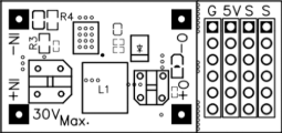
 Design with SY8205 in Cirkit Designer
Introduction
The SY8205 is a high-efficiency step-down (buck) DC-DC converter designed for low-power applications. It is capable of converting a higher input voltage to a lower, regulated output voltage with high efficiency. The SY8205 features a wide input voltage range, adjustable output voltage, and built-in protection mechanisms such as overcurrent protection and thermal shutdown. These features make it ideal for use in battery-powered devices, portable electronics, and other compact electronic systems requiring efficient power regulation.
Explore Projects Built with SY8205
 Open Project in Cirkit Designer
 Open Project in Cirkit Designer
 Open Project in Cirkit Designer
 Open Project in Cirkit Designer
Explore Projects Built with SY8205
Open Project in Cirkit DesignerOpen Project in Cirkit DesignerOpen Project in Cirkit DesignerOpen Project in Cirkit DesignerCommon Applications
- Battery-powered devices (e.g., smartphones, tablets, and wearables)
- Portable electronics
- Embedded systems and microcontroller-based circuits
- Low-power IoT devices
- Power supply modules for sensors and small motors
Technical Specifications
Key Specifications
| Parameter | Value |
|---|---|
| Input Voltage Range | 4.5V to 18V |
| Output Voltage Range | Adjustable (0.6V to VIN) |
| Output Current | Up to 3A |
| Switching Frequency | 1.5MHz |
| Efficiency | Up to 95% |
| Feedback Voltage | 0.6V |
| Operating Temperature Range | -40°C to +85°C |
| Protection Features | Overcurrent, thermal shutdown |
Pin Configuration and Descriptions
The SY8205 is typically available in a small SOT23-6 package. Below is the pinout and description:
| Pin Number | Pin Name | Description |
|---|---|---|
| 1 | VIN | Input voltage pin. Connect to the input power source (4.5V to 18V). |
| 2 | GND | Ground pin. Connect to the system ground. |
| 3 | SW | Switching node. Connect to the inductor and output capacitor. |
| 4 | FB | Feedback pin. Connect to a resistor divider to set the output voltage. |
| 5 | EN | Enable pin. Drive high to enable the converter, low to disable it. |
| 6 | BST | Bootstrap pin. Connect a capacitor between BST and SW for high-side drive. |
Usage Instructions
How to Use the SY8205 in a Circuit
- Input Voltage: Ensure the input voltage (VIN) is within the range of 4.5V to 18V.
- Output Voltage Setting: Use a resistor divider network connected to the FB pin to set the desired output voltage. The output voltage can be calculated using the formula: [ V_{OUT} = V_{FB} \times \left(1 + \frac{R1}{R2}\right) ] where ( V_{FB} ) is the feedback voltage (0.6V), ( R1 ) is the resistor connected between the output and FB pin, and ( R2 ) is the resistor connected between the FB pin and ground.
- Inductor and Capacitor Selection: Choose an inductor and output capacitor based on the desired output current and voltage ripple. Refer to the datasheet for recommended values.
- Enable Pin: Drive the EN pin high (logic level) to enable the converter. Pull it low to disable the output.
- Bootstrap Capacitor: Connect a small ceramic capacitor (typically 0.1µF) between the BST and SW pins to ensure proper operation of the high-side MOSFET.
Important Considerations
- Thermal Management: Ensure adequate heat dissipation, especially when operating at high currents. Use a PCB with good thermal conductivity.
- Input Capacitor: Place a low-ESR ceramic capacitor close to the VIN pin to reduce input voltage ripple.
- PCB Layout: Minimize the loop area of the input capacitor, inductor, and output capacitor to reduce noise and improve efficiency.
Example: Using the SY8205 with an Arduino UNO
The SY8205 can be used to power an Arduino UNO by stepping down a higher voltage (e.g., 12V) to 5V. Below is an example circuit and Arduino code to enable/disable the SY8205 using a digital pin.
Circuit Connections
- Connect the VIN pin of the SY8205 to a 12V power source.
- Set the output voltage to 5V using a resistor divider on the FB pin.
- Connect the output of the SY8205 to the 5V pin of the Arduino UNO.
- Connect the EN pin of the SY8205 to a digital pin (e.g., D7) of the Arduino UNO.
Arduino Code
// Arduino code to control the SY8205 enable pin
const int enablePin = 7; // Digital pin connected to SY8205 EN pin

void setup() {
  pinMode(enablePin, OUTPUT); // Set the enable pin as an output
  digitalWrite(enablePin, HIGH); // Enable the SY8205 (output is active)
}

void loop() {
  // Example: Toggle the SY8205 output every 5 seconds
  digitalWrite(enablePin, LOW); // Disable the SY8205
  delay(5000); // Wait for 5 seconds
  digitalWrite(enablePin, HIGH); // Enable the SY8205
  delay(5000); // Wait for 5 seconds
}
Troubleshooting and FAQs
Common Issues and Solutions
No Output Voltage
- Cause: The EN pin is not driven high.
- Solution: Ensure the EN pin is connected to a logic high signal or VIN through a pull-up resistor.
Output Voltage is Incorrect
- Cause: Incorrect resistor values in the feedback network.
- Solution: Verify the resistor divider values and recalculate the output voltage using the formula provided.
Excessive Heat
- Cause: High output current or poor thermal management.
- Solution: Use a heatsink or improve PCB thermal design. Ensure the input and output capacitors are properly rated.
High Output Ripple
- Cause: Inadequate output capacitor or poor PCB layout.
- Solution: Use a low-ESR capacitor and minimize the loop area in the PCB layout.
FAQs
Q1: Can the SY8205 operate without a load?
A1: Yes, the SY8205 can operate without a load, but ensure the feedback network is properly configured.
Q2: What happens if the input voltage exceeds 18V?
A2: The SY8205 may be damaged if the input voltage exceeds its maximum rating. Use a voltage regulator or zener diode to protect the input.
Q3: Can the SY8205 be used for 3.3V output?
A3: Yes, the SY8205 can be configured for a 3.3V output by selecting appropriate resistor values for the feedback network.
This concludes the documentation for the SY8205. For further details, refer to the component datasheet or contact the manufacturer.