How to Use USB to CAN Adapter: Examples, Pinouts, and Specs
Introduction
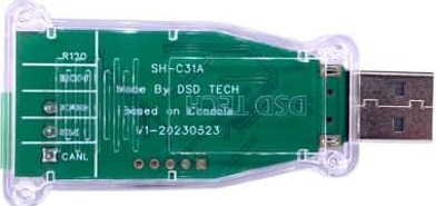
The DSD TECH SH-C31A USB to CAN Adapter with FD Support, based on the Canable 2.0 design, is a versatile device that bridges the gap between a USB port on a computer and a Controller Area Network (CAN). This adapter enables seamless communication, data transfer, and control of CAN devices, making it an essential tool for automotive diagnostics, industrial automation, and embedded system development.
Explore Projects Built with USB to CAN Adapter
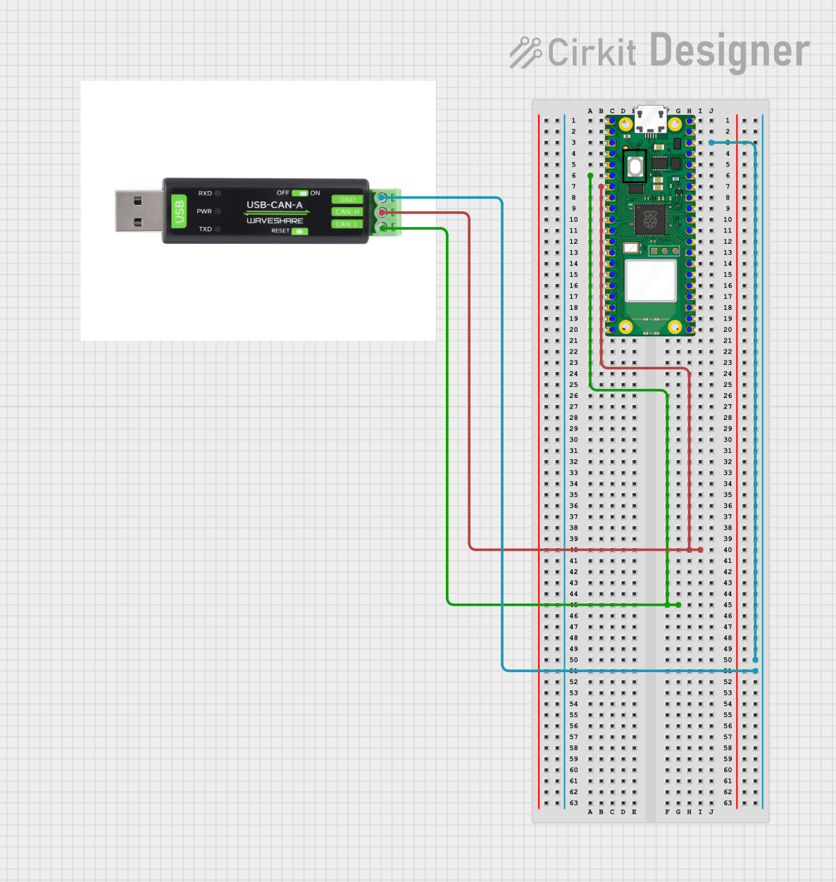

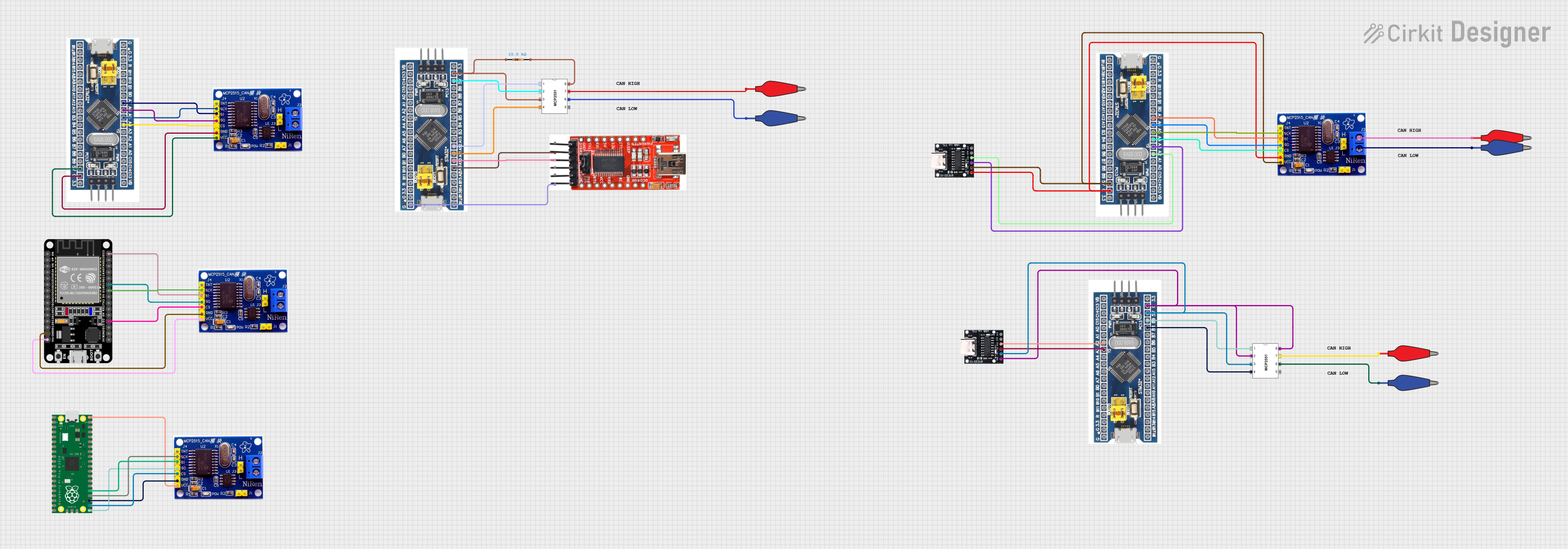
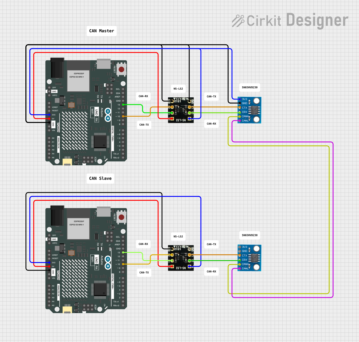
Explore Projects Built with USB to CAN Adapter
Common Applications and Use Cases
- Automotive diagnostics and debugging
- Industrial automation and control systems
- Embedded system development and testing
- Real-time monitoring of CAN bus data
- Prototyping and development of CAN-based devices
Technical Specifications
The following table outlines the key technical details of the SH-C31A USB to CAN Adapter:
| Specification | Details |
|---|---|
| Manufacturer | DSD TECH |
| Model | SH-C31A |
| CAN Protocol Support | CAN 2.0A, CAN 2.0B, and CAN FD |
| USB Interface | USB 2.0 (Type-A) |
| CAN Baud Rate | 10 kbps to 1 Mbps (Classical CAN), up to 8 Mbps (CAN FD) |
| Operating Voltage | 5V (via USB) |
| Current Consumption | < 100 mA |
| Operating Temperature | -20°C to 70°C |
| Dimensions | 60 mm x 20 mm x 10 mm |
| Supported Operating Systems | Windows, Linux, macOS |
| Firmware | Open-source firmware based on Canable 2.0 |
Pin Configuration and Descriptions
The SH-C31A USB to CAN Adapter features a DB9 connector for CAN communication. The pinout is as follows:
| Pin Number | Signal Name | Description |
|---|---|---|
| 1 | NC | Not connected |
| 2 | CAN_L | CAN Low signal |
| 3 | GND | Ground |
| 4 | NC | Not connected |
| 5 | Shield | Shield (optional grounding) |
| 6 | GND | Ground |
| 7 | CAN_H | CAN High signal |
| 8 | NC | Not connected |
| 9 | NC | Not connected |
Usage Instructions
How to Use the SH-C31A in a Circuit
- Connect the Adapter to a Computer: Plug the USB connector into an available USB port on your computer.
- Install Drivers:
- For Windows, download and install the appropriate drivers from the DSD TECH website.
- For Linux and macOS, the adapter is typically recognized as a USB-CAN device without additional drivers.
- Connect to the CAN Bus:
- Use the DB9 connector to interface with the CAN bus.
- Connect
CAN_Hto the CAN High line andCAN_Lto the CAN Low line of your CAN network.
- Configure the Adapter:
- Use software tools like
candlelight,CANable GUI, orSocketCAN(Linux) to configure the baud rate and other parameters.
- Use software tools like
- Monitor and Transmit Data:
- Use compatible software to monitor CAN messages or transmit data to the CAN bus.
Important Considerations and Best Practices
- Termination Resistor: Ensure that the CAN bus is properly terminated with 120-ohm resistors at both ends of the bus.
- Power Supply: The adapter is powered via USB, so no external power supply is required.
- Firmware Updates: Check for firmware updates on the DSD TECH website to ensure compatibility with the latest CAN standards.
- Isolation: The SH-C31A does not provide galvanic isolation. For high-voltage environments, consider using an isolated USB to CAN adapter.
Example: Using the Adapter with an Arduino UNO
The SH-C31A can be used with an Arduino UNO to monitor CAN messages. Below is an example of how to set up the adapter with the Arduino IDE:
#include <SPI.h>
#include <mcp2515.h> // Include the MCP2515 CAN library

MCP2515 mcp2515(10); // Set the CS pin to 10 for the MCP2515 CAN controller

void setup() {
  Serial.begin(9600); // Initialize serial communication
  SPI.begin();        // Initialize SPI communication

  // Initialize the MCP2515 CAN controller
  if (mcp2515.reset() != MCP2515::ERROR_OK) {
    Serial.println("MCP2515 reset failed!");
    while (1);
  }

  // Set the CAN speed to 500 kbps
  if (mcp2515.setBitrate(CAN_500KBPS) != MCP2515::ERROR_OK) {
    Serial.println("Failed to set CAN bitrate!");
    while (1);
  }

  // Set the MCP2515 to normal mode
  if (mcp2515.setNormalMode() != MCP2515::ERROR_OK) {
    Serial.println("Failed to set normal mode!");
    while (1);
  }

  Serial.println("MCP2515 initialized successfully!");
}

void loop() {
  CAN_message_t message;

  // Check if a new CAN message is available
  if (mcp2515.readMessage(&message) == MCP2515::ERROR_OK) {
    Serial.print("Message ID: ");
    Serial.println(message.id, HEX);

    Serial.print("Data: ");
    for (int i = 0; i < message.len; i++) {
      Serial.print(message.data[i], HEX);
      Serial.print(" ");
    }
    Serial.println();
  }
}
Notes:
- Ensure the MCP2515 CAN module is connected to the Arduino UNO.
- The SH-C31A adapter can be used to monitor the CAN bus activity generated by the Arduino.
Troubleshooting and FAQs
Common Issues and Solutions
Adapter Not Recognized by the Computer:
- Ensure the USB cable is properly connected.
- Install the correct drivers for your operating system.
- Try a different USB port or cable.
No CAN Messages Detected:
- Verify the CAN bus wiring and ensure proper termination with 120-ohm resistors.
- Check the baud rate configuration of the adapter and the CAN network.
Data Corruption or Errors:
- Ensure the CAN_H and CAN_L lines are not swapped.
- Avoid long or improperly shielded cables that may introduce noise.
Firmware Update Issues:
- Follow the firmware update instructions provided by DSD TECH carefully.
- Ensure the adapter is not disconnected during the update process.
FAQs
Q: Can the SH-C31A be used with Raspberry Pi?
A: Yes, the adapter is compatible with Raspberry Pi using the SocketCAN interface on Linux.
Q: Does the adapter support CAN FD?
A: Yes, the SH-C31A supports CAN FD with data rates up to 8 Mbps.
Q: Is the adapter compatible with third-party CAN software?
A: Yes, it works with popular tools like candlelight, CANable GUI, and SocketCAN.
Q: Can I use the adapter for automotive diagnostics?
A: Yes, the SH-C31A is suitable for automotive diagnostics, provided the software supports the required protocols.