Cirkit Designer
Your all-in-one circuit design IDE
Home /
Component Documentation
How to Use 4 Channel Infrared Tracing Module: Examples, Pinouts, and Specs
Introduction
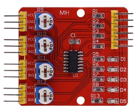
The 4 Channel Infrared Tracing Module is a sensor module designed for line-following robots. It is capable of detecting infrared light to trace lines on a surface, making it an essential component for robotics projects that require precise path-following capabilities. This module is widely used in educational robotics, hobby projects, and automated guided vehicles (AGVs).
Explore Projects Built with 4 Channel Infrared Tracing Module
Arduino-Based Obstacle Avoiding and Line Following Robot with IR and Ultrasonic Sensors
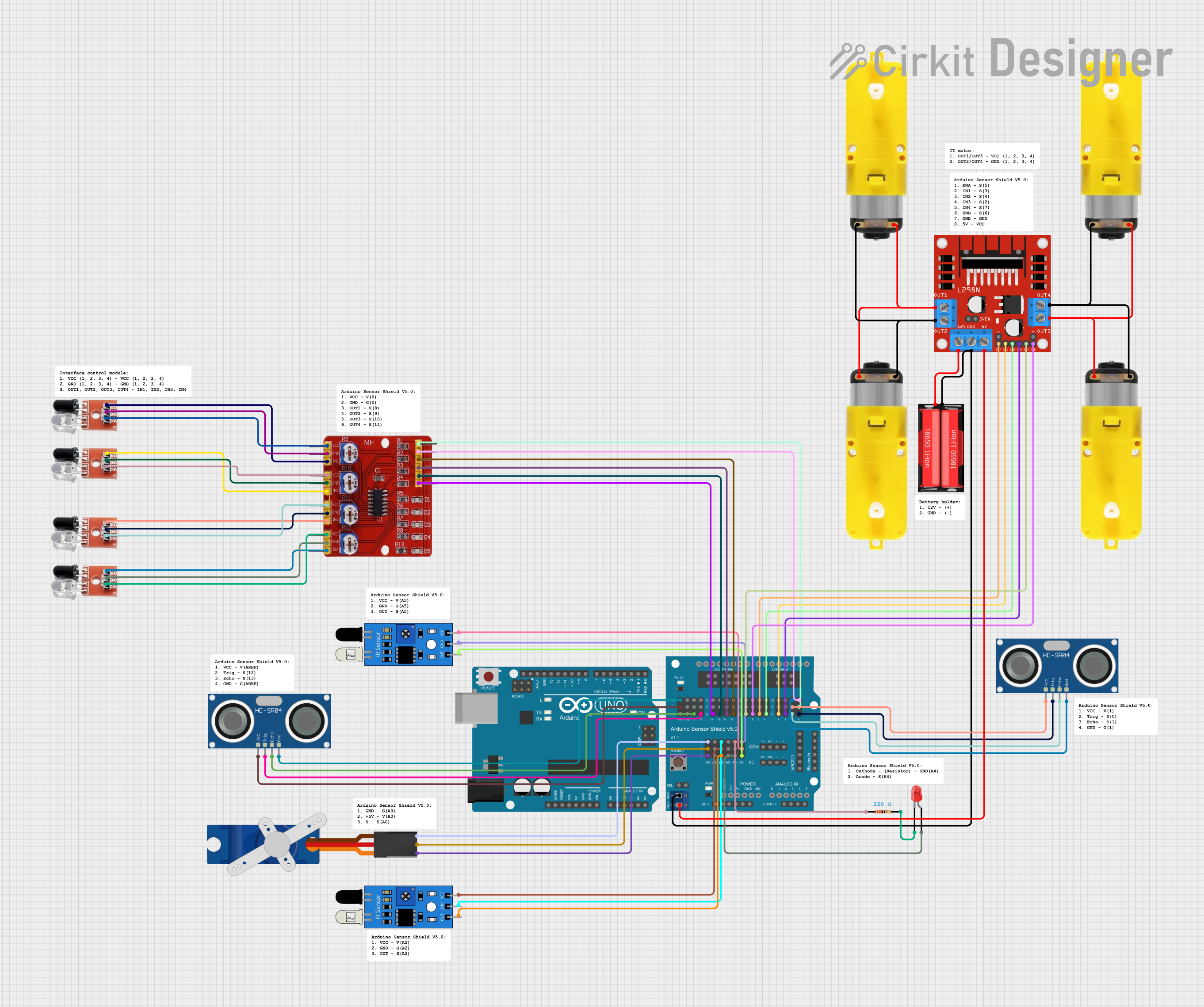
This circuit is a robotic system that uses an Arduino UNO and various sensors, including infrared, ultrasonic, and obstacle avoidance sensors, to detect and navigate its environment. It controls multiple motors through an L298N motor driver and includes a servo motor for additional movement capabilities. The system is powered by a 18650 Li-Ion battery and features an LED indicator.
Arduino UNO-Based Line Following Robot with NRF24L01 Wireless Control and Battery Power
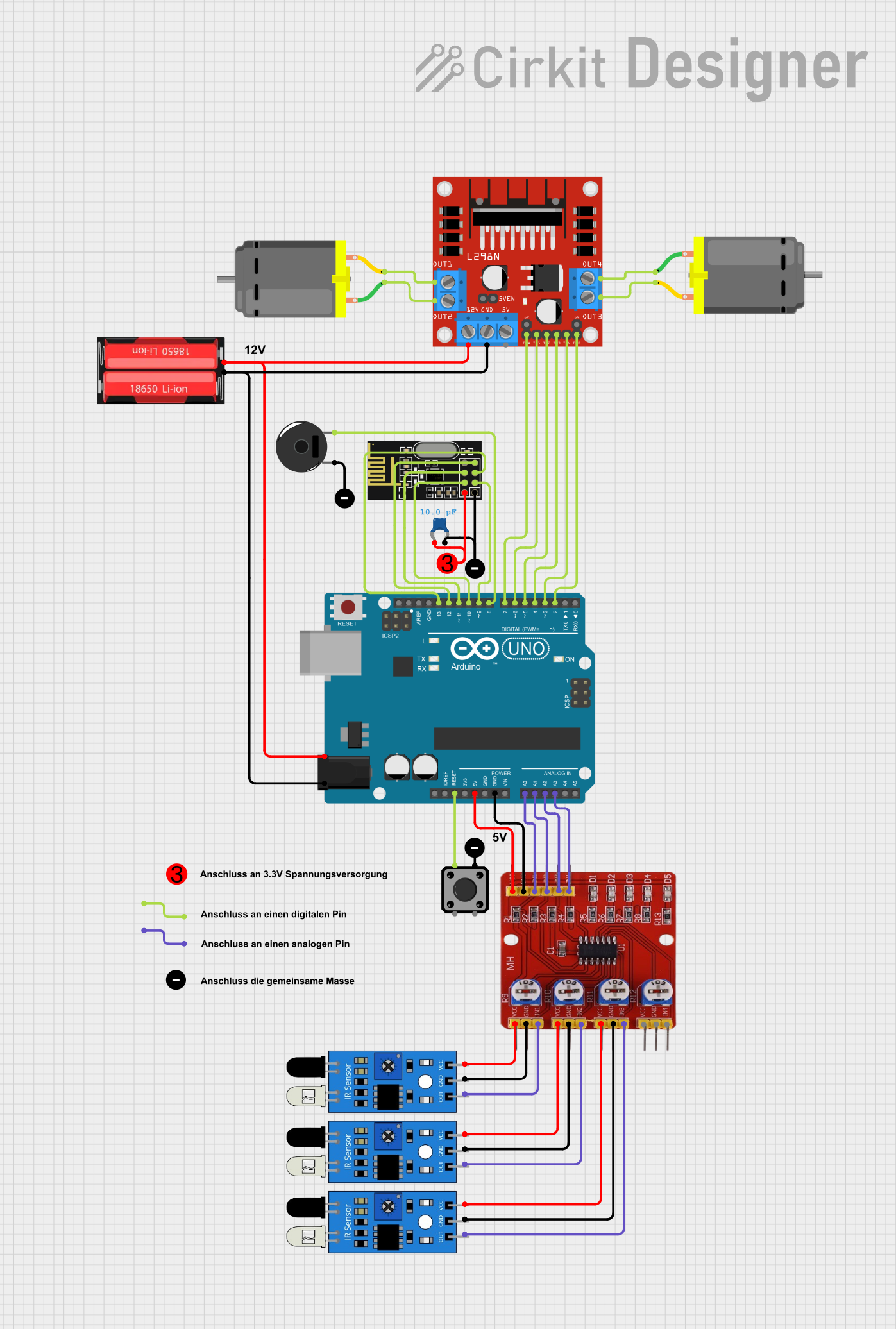
This circuit is a remote-controlled vehicle system that uses an Arduino UNO to interface with an NRF24L01 wireless module for communication, a 4-channel infrared tracing module for line detection, and an L298N motor driver to control two DC motors. Additional components include IR sensors for obstacle detection, a tactile switch for reset, and a piezo buzzer for audio feedback.
Raspberry Pi 4B-Based Multi-Sensor Monitoring System with GPS and Ultrasonic Sensing
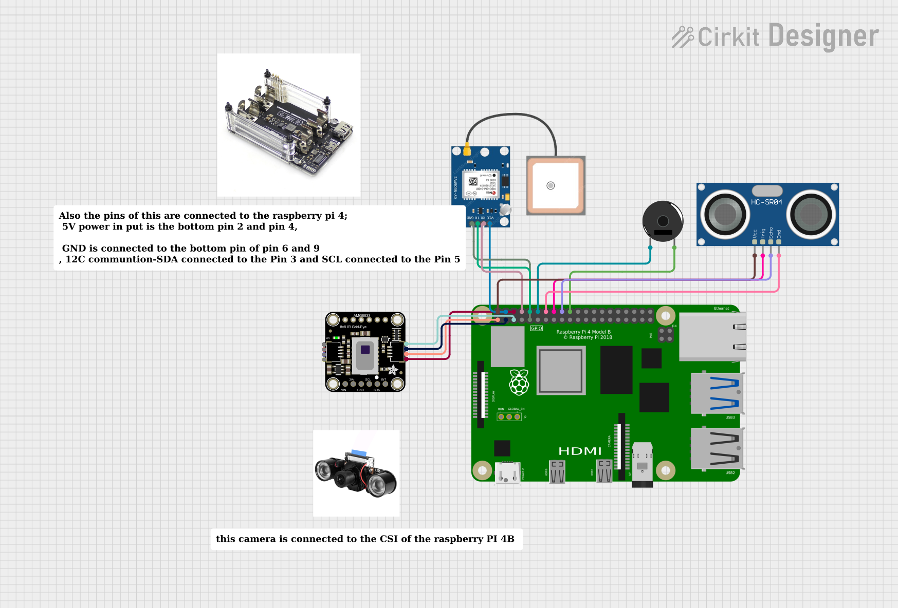
This circuit features a Raspberry Pi 4B as the central processing unit, interfaced with an Adafruit AMG8833 infrared thermal camera and a GPS NEO 6M module for location tracking. The Raspberry Pi also controls a Piezo Buzzer for audio feedback and an HC-SR04 Ultrasonic Sensor for distance measurement. The circuit is likely designed for applications requiring environmental sensing, location tracking, and proximity detection, with audible alerts provided by the buzzer.
Arduino UNO Based IR-Controlled Relay Switching System
This circuit is designed to control multiple relay channels using an Arduino UNO, which is programmed to respond to IR remote control signals. The Arduino UNO is connected to a 4-channel 5V relay module and a single 5V relay, allowing for the switching of various devices or loads. The TSOP312 IR receiver is interfaced with the Arduino to receive the IR signals, which then triggers the corresponding relays based on the received commands.
Explore Projects Built with 4 Channel Infrared Tracing Module
Arduino-Based Obstacle Avoiding and Line Following Robot with IR and Ultrasonic Sensors
This circuit is a robotic system that uses an Arduino UNO and various sensors, including infrared, ultrasonic, and obstacle avoidance sensors, to detect and navigate its environment. It controls multiple motors through an L298N motor driver and includes a servo motor for additional movement capabilities. The system is powered by a 18650 Li-Ion battery and features an LED indicator.
Arduino UNO-Based Line Following Robot with NRF24L01 Wireless Control and Battery Power
This circuit is a remote-controlled vehicle system that uses an Arduino UNO to interface with an NRF24L01 wireless module for communication, a 4-channel infrared tracing module for line detection, and an L298N motor driver to control two DC motors. Additional components include IR sensors for obstacle detection, a tactile switch for reset, and a piezo buzzer for audio feedback.
Raspberry Pi 4B-Based Multi-Sensor Monitoring System with GPS and Ultrasonic Sensing
This circuit features a Raspberry Pi 4B as the central processing unit, interfaced with an Adafruit AMG8833 infrared thermal camera and a GPS NEO 6M module for location tracking. The Raspberry Pi also controls a Piezo Buzzer for audio feedback and an HC-SR04 Ultrasonic Sensor for distance measurement. The circuit is likely designed for applications requiring environmental sensing, location tracking, and proximity detection, with audible alerts provided by the buzzer.
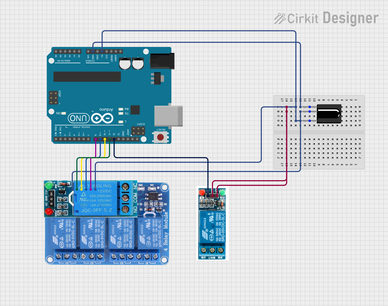
Arduino UNO Based IR-Controlled Relay Switching System
This circuit is designed to control multiple relay channels using an Arduino UNO, which is programmed to respond to IR remote control signals. The Arduino UNO is connected to a 4-channel 5V relay module and a single 5V relay, allowing for the switching of various devices or loads. The TSOP312 IR receiver is interfaced with the Arduino to receive the IR signals, which then triggers the corresponding relays based on the received commands.
Technical Specifications
Key Technical Details
| Parameter | Value |
|---|---|
| Operating Voltage | 3.3V - 5V |
| Operating Current | 20mA |
| Output Type | Digital (High/Low) |
| Detection Range | 0.1cm - 3cm |
| Dimensions | 50mm x 20mm x 10mm |
| Weight | 10g |
Pin Configuration and Descriptions
| Pin Number | Pin Name | Description |
|---|---|---|
| 1 | VCC | Power supply (3.3V - 5V) |
| 2 | GND | Ground |
| 3 | OUT1 | Digital output for sensor 1 (High/Low) |
| 4 | OUT2 | Digital output for sensor 2 (High/Low) |
| 5 | OUT3 | Digital output for sensor 3 (High/Low) |
| 6 | OUT4 | Digital output for sensor 4 (High/Low) |
Usage Instructions
How to Use the Component in a Circuit
- Power Supply: Connect the VCC pin to a 3.3V or 5V power supply and the GND pin to the ground of your circuit.
- Outputs: Connect the OUT1, OUT2, OUT3, and OUT4 pins to the digital input pins of your microcontroller (e.g., Arduino UNO).
- Placement: Place the module such that the infrared sensors are facing the surface with the line to be followed.
Important Considerations and Best Practices
- Surface and Line: Ensure the surface is non-reflective and the line is of a contrasting color to the surface for optimal detection.
- Height Adjustment: Adjust the height of the module from the surface to be within the detection range (0.1cm - 3cm).
- Calibration: Calibrate the sensors if necessary to account for varying lighting conditions and surface textures.
Sample Arduino Code
// Sample code to read values from the 4 Channel Infrared Tracing Module
// and print them to the Serial Monitor.

const int sensor1Pin = 2; // Connect OUT1 to digital pin 2
const int sensor2Pin = 3; // Connect OUT2 to digital pin 3
const int sensor3Pin = 4; // Connect OUT3 to digital pin 4
const int sensor4Pin = 5; // Connect OUT4 to digital pin 5

void setup() {
  Serial.begin(9600); // Initialize serial communication at 9600 baud rate
  pinMode(sensor1Pin, INPUT); // Set sensor pins as input
  pinMode(sensor2Pin, INPUT);
  pinMode(sensor3Pin, INPUT);
  pinMode(sensor4Pin, INPUT);
}

void loop() {
  int sensor1Value = digitalRead(sensor1Pin); // Read sensor values
  int sensor2Value = digitalRead(sensor2Pin);
  int sensor3Value = digitalRead(sensor3Pin);
  int sensor4Value = digitalRead(sensor4Pin);

  // Print sensor values to Serial Monitor
  Serial.print("Sensor 1: ");
  Serial.print(sensor1Value);
  Serial.print(" | Sensor 2: ");
  Serial.print(sensor2Value);
  Serial.print(" | Sensor 3: ");
  Serial.print(sensor3Value);
  Serial.print(" | Sensor 4: ");
  Serial.println(sensor4Value);

  delay(100); // Small delay to avoid flooding the Serial Monitor
}
Troubleshooting and FAQs
Common Issues Users Might Face
No Detection: The module does not detect the line.
- Solution: Ensure the module is powered correctly and the sensors are within the detection range. Check the surface and line contrast.
False Positives: The module detects lines where there are none.
- Solution: Reduce ambient light interference and ensure the surface is non-reflective.
Inconsistent Readings: The sensor values fluctuate.
- Solution: Stabilize the module's height and ensure a consistent surface texture. Calibrate the sensors if necessary.
Solutions and Tips for Troubleshooting
- Power Supply: Ensure a stable power supply to avoid erratic sensor behavior.
- Wiring: Double-check all connections to ensure they are secure and correct.
- Environment: Minimize external infrared sources and reflective surfaces that may interfere with the sensor readings.
By following this documentation, users can effectively integrate and utilize the 4 Channel Infrared Tracing Module in their line-following robot projects, ensuring accurate and reliable performance.