How to Use INA226-: Examples, Pinouts, and Specs
Introduction
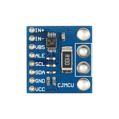
The INA226 is a high-side current shunt monitor with an integrated I2C interface, manufactured by ESP (Part ID: 32). It is designed for precise current sensing and power monitoring in a variety of applications. The INA226 can measure both current and voltage, enabling real-time power calculations. Its wide input voltage range and high accuracy make it ideal for power management systems, battery monitoring, and industrial automation.
Explore Projects Built with INA226-


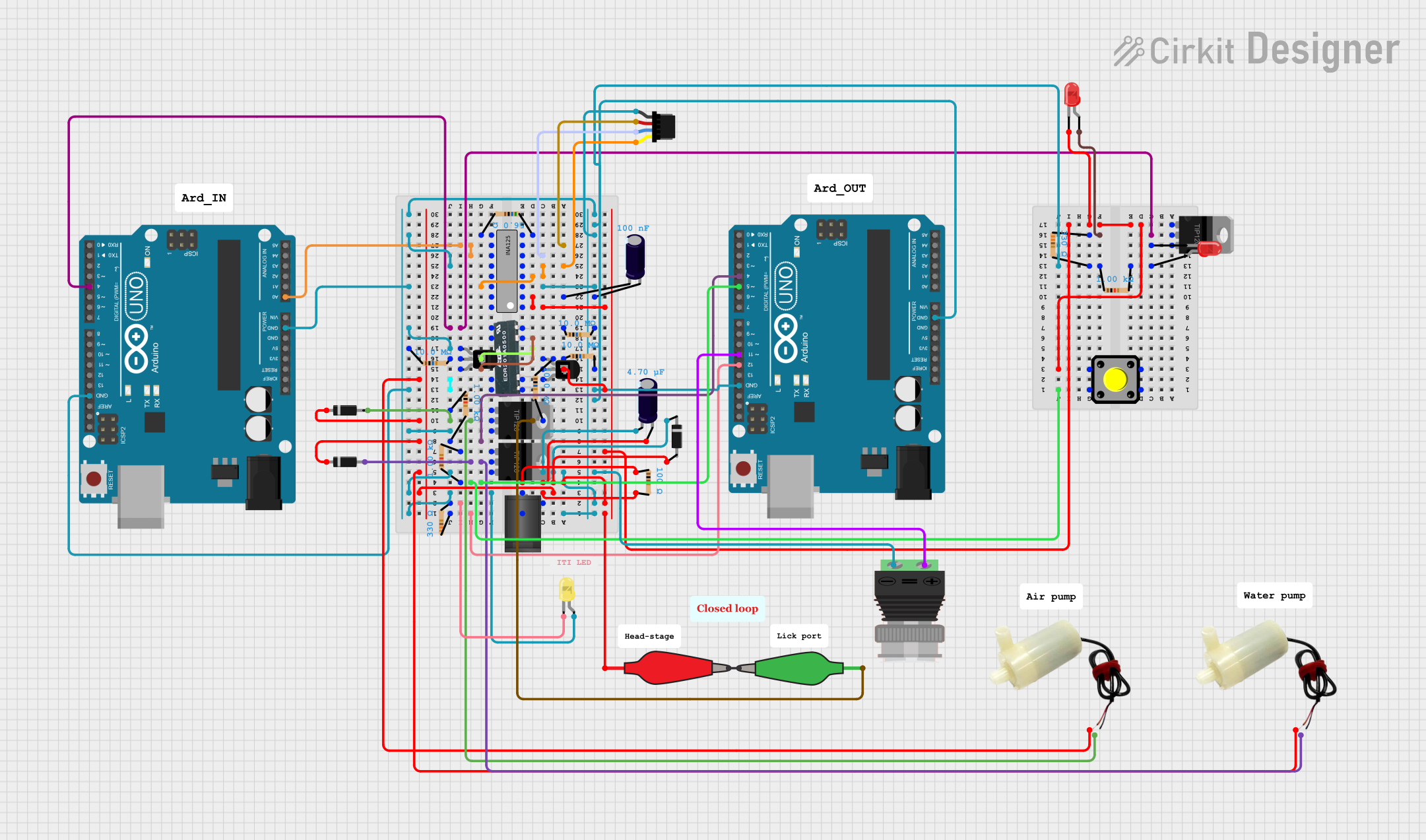
Explore Projects Built with INA226-
Common Applications
- Power management in embedded systems
- Battery monitoring in portable devices
- Energy metering in industrial equipment
- Solar power systems
- Data center power monitoring
Technical Specifications
Key Technical Details
| Parameter | Value |
|---|---|
| Supply Voltage (Vcc) | 2.7V to 5.5V |
| Input Voltage Range | 0V to 36V |
| Current Measurement Range | Configurable via external shunt resistor |
| Communication Interface | I2C (up to 400 kHz) |
| Accuracy | ±0.1% (typical) |
| Operating Temperature | -40°C to +125°C |
| Power Consumption | 330 µA (typical) |
Pin Configuration and Descriptions
| Pin Name | Pin Number | Description |
|---|---|---|
| V+ | 1 | Positive supply voltage (2.7V to 5.5V) |
| GND | 2 | Ground |
| SCL | 3 | I2C clock line |
| SDA | 4 | I2C data line |
| VIN+ | 5 | Positive input for current sensing |
| VIN- | 6 | Negative input for current sensing |
| ALERT | 7 | Alert output for programmable thresholds |
| ADDR | 8 | I2C address configuration |
Usage Instructions
How to Use the INA226 in a Circuit
- Power Supply: Connect the V+ pin to a 2.7V to 5.5V power source and the GND pin to ground.
- Current Sensing: Place a shunt resistor between the VIN+ and VIN- pins. The voltage drop across this resistor will be used to calculate the current.
- I2C Communication: Connect the SCL and SDA pins to the corresponding I2C lines of your microcontroller. Use pull-up resistors (typically 4.7 kΩ) on these lines.
- I2C Address: Configure the I2C address using the ADDR pin. Refer to the datasheet for address selection options.
- Alert Function: If needed, connect the ALERT pin to a microcontroller GPIO to monitor programmable thresholds.
Important Considerations
- Shunt Resistor Selection: Choose a resistor with a low temperature coefficient and appropriate power rating to ensure accurate measurements.
- Bypass Capacitor: Place a 0.1 µF ceramic capacitor close to the V+ pin to stabilize the power supply.
- I2C Pull-Up Resistors: Ensure proper pull-up resistors are used on the SCL and SDA lines for reliable communication.
- Input Voltage Range: Ensure the voltage at VIN+ and VIN- does not exceed the specified range (0V to 36V).
Example Code for Arduino UNO
Below is an example of how to interface the INA226 with an Arduino UNO to measure current and voltage:
#include <Wire.h>

#define INA226_ADDRESS 0x40  // Default I2C address of INA226

void setup() {
  Wire.begin();  // Initialize I2C communication
  Serial.begin(9600);  // Initialize serial communication for debugging

  // Configure INA226 (example: set calibration register)
  Wire.beginTransmission(INA226_ADDRESS);
  Wire.write(0x05);  // Calibration register address
  Wire.write(0x10);  // High byte of calibration value
  Wire.write(0x00);  // Low byte of calibration value
  Wire.endTransmission();
}

void loop() {
  // Request voltage data from INA226
  Wire.beginTransmission(INA226_ADDRESS);
  Wire.write(0x02);  // Bus voltage register address
  Wire.endTransmission();
  Wire.requestFrom(INA226_ADDRESS, 2);  // Request 2 bytes of data

  if (Wire.available() == 2) {
    uint16_t rawVoltage = (Wire.read() << 8) | Wire.read();
    float busVoltage = rawVoltage * 1.25 / 1000;  // Convert to volts
    Serial.print("Bus Voltage: ");
    Serial.print(busVoltage);
    Serial.println(" V");
  }

  delay(1000);  // Wait 1 second before next reading
}
Notes on the Code
- Replace the calibration value in the setup function with the appropriate value for your shunt resistor.
- The bus voltage conversion factor (1.25 mV per LSB) is based on the INA226 datasheet.
Troubleshooting and FAQs
Common Issues and Solutions
No I2C Communication:
- Ensure the SCL and SDA lines have proper pull-up resistors (4.7 kΩ recommended).
- Verify the I2C address matches the configuration of the ADDR pin.
Incorrect Current Readings:
- Check the shunt resistor value and ensure it matches the calibration settings in your code.
- Verify the connections to the VIN+ and VIN- pins.
Alert Pin Not Functioning:
- Ensure the ALERT pin is properly configured in the INA226 registers.
- Check the microcontroller GPIO pin configuration.
High Noise in Measurements:
- Add a bypass capacitor (0.1 µF) close to the V+ pin.
- Use shielded cables for long connections to reduce EMI.
FAQs
Q: Can the INA226 measure negative currents?
A: No, the INA226 is designed for high-side current sensing and measures only positive currents.
Q: What is the maximum current the INA226 can measure?
A: The maximum current depends on the shunt resistor value and the input voltage range. Ensure the voltage drop across the shunt does not exceed the input range of the INA226.
Q: Can I use the INA226 with a 3.3V microcontroller?
A: Yes, the INA226 operates with a supply voltage of 2.7V to 5.5V and is compatible with 3.3V logic levels.
Q: How do I calculate power using the INA226?
A: Power can be calculated by multiplying the measured current and bus voltage. The INA226 can also perform this calculation internally and provide the result via I2C.