How to Use ESP32 WROOM 38 PINS: Examples, Pinouts, and Specs
Introduction
The ESP32 WROOM 38 PINS is a powerful microcontroller module designed for IoT (Internet of Things) applications. It features integrated Wi-Fi and Bluetooth capabilities, making it ideal for wireless communication and control. With 38 GPIO (General Purpose Input/Output) pins, the ESP32 WROOM offers extensive connectivity options for sensors, actuators, and other peripherals. Its high performance, low power consumption, and versatility make it a popular choice for hobbyists, developers, and engineers.
Explore Projects Built with ESP32 WROOM 38 PINS


Explore Projects Built with ESP32 WROOM 38 PINS
Common Applications and Use Cases
- Smart home automation systems
- IoT devices and wireless sensor networks
- Robotics and motor control
- Wearable devices
- Industrial automation
- Data logging and remote monitoring
Technical Specifications
The ESP32 WROOM 38 PINS module is built on the ESP32 chip, which includes dual-core processors and a rich set of peripherals. Below are the key technical details:
Key Technical Details
- Processor: Dual-core Xtensa® 32-bit LX6 microprocessor
- Clock Speed: Up to 240 MHz
- Flash Memory: 4 MB (varies by model)
- SRAM: 520 KB
- Wi-Fi: 802.11 b/g/n (2.4 GHz)
- Bluetooth: v4.2 BR/EDR and BLE
- Operating Voltage: 3.3V
- GPIO Pins: 38 (multipurpose, including ADC, DAC, PWM, I2C, SPI, UART)
- ADC Channels: 18 (12-bit resolution)
- DAC Channels: 2
- PWM Channels: 16
- Operating Temperature: -40°C to 85°C
- Power Consumption: Ultra-low power in deep sleep mode (~10 µA)
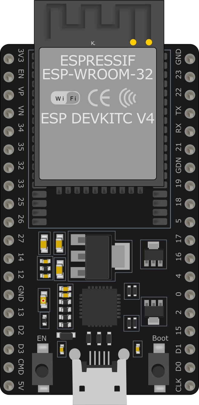
Pin Configuration and Descriptions
The ESP32 WROOM 38 PINS module has 38 GPIO pins, each with specific functions. Below is a table summarizing the pin configuration:
| Pin Number | Pin Name | Function |
|---|---|---|
| 1 | EN | Enable pin (active high) |
| 2 | IO0 | GPIO0, boot mode selection |
| 3 | IO1 (TX0) | GPIO1, UART0 TX |
| 4 | IO3 (RX0) | GPIO3, UART0 RX |
| 5 | IO4 | GPIO4, PWM, ADC |
| 6 | IO5 | GPIO5, PWM, ADC |
| 7 | IO12 | GPIO12, ADC, touch sensor |
| 8 | IO13 | GPIO13, ADC, touch sensor |
| 9 | IO14 | GPIO14, PWM, ADC |
| 10 | IO15 | GPIO15, PWM, ADC |
| ... | ... | ... (Refer to the datasheet for full) |
Note: Some GPIO pins have specific restrictions or are used during boot. Refer to the ESP32 datasheet for detailed pin functions.
Usage Instructions
How to Use the ESP32 WROOM 38 PINS in a Circuit
Powering the Module:
- The ESP32 WROOM operates at 3.3V. Use a voltage regulator if your power source exceeds this voltage.
- Connect the
ENpin to 3.3V to enable the module.
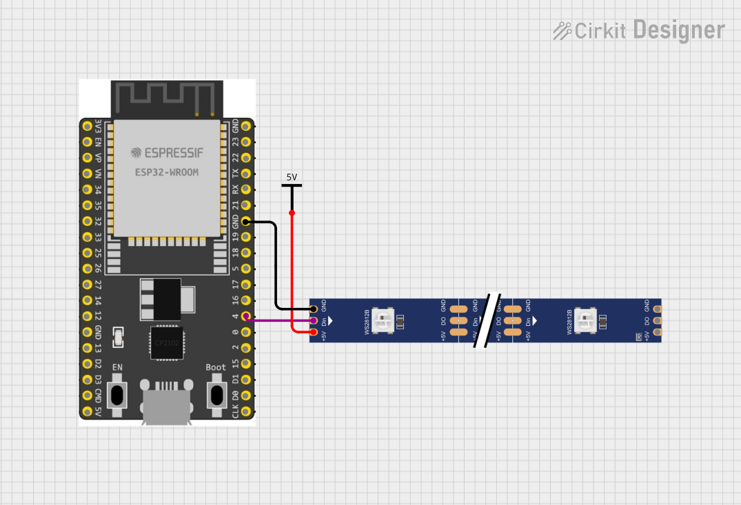
Connecting Peripherals:
- Use the GPIO pins to connect sensors, actuators, or other devices. Ensure the voltage levels of connected devices are compatible with 3.3V logic.
Programming the ESP32:
- The ESP32 can be programmed using the Arduino IDE or the ESP-IDF (Espressif IoT Development Framework).
- Connect the module to your computer via a USB-to-serial adapter. Use GPIO0 to set the module into boot mode for flashing firmware.
Important Considerations and Best Practices
- Avoid using GPIO6 to GPIO11 as they are connected to the internal flash memory.
- Use pull-up or pull-down resistors for pins that require stable logic levels.
- For Wi-Fi applications, ensure the antenna has sufficient clearance from other components to avoid signal interference.
- Use deep sleep mode to minimize power consumption in battery-powered applications.
Example Code for Arduino IDE
Below is an example of how to blink an LED connected to GPIO2 using the Arduino IDE:
// Define the GPIO pin for the LED
#define LED_PIN 2

void setup() {
  // Initialize the LED pin as an output
  pinMode(LED_PIN, OUTPUT);
}

void loop() {
  // Turn the LED on
  digitalWrite(LED_PIN, HIGH);
  delay(1000); // Wait for 1 second

  // Turn the LED off
  digitalWrite(LED_PIN, LOW);
  delay(1000); // Wait for 1 second
}
Tip: Install the ESP32 board package in the Arduino IDE before uploading code. Go to
File > Preferences, add the ESP32 board URL, and install the package via the Board Manager.
Troubleshooting and FAQs
Common Issues and Solutions
ESP32 Not Detected by Computer:
- Ensure the USB-to-serial adapter drivers are installed.
- Check the connections and ensure the module is powered correctly.
Cannot Upload Code:
- Hold the
BOOTbutton (connected to GPIO0) while uploading code to enter boot mode. - Verify the correct COM port and board are selected in the Arduino IDE.
- Hold the
Wi-Fi Connection Fails:
- Check the SSID and password in your code.
- Ensure the Wi-Fi signal strength is sufficient.
Module Overheats:
- Verify the input voltage is within the acceptable range (3.3V).
- Avoid short circuits on the GPIO pins.
FAQs
Q: Can I power the ESP32 WROOM with 5V?
A: No, the ESP32 operates at 3.3V. Use a voltage regulator to step down 5V to 3.3V.Q: How many devices can I connect via Bluetooth?
A: The ESP32 supports up to 7 Bluetooth devices simultaneously in BLE mode.Q: Can I use the ESP32 for audio applications?
A: Yes, the ESP32 has I2S support for audio input/output.Q: How do I reset the ESP32?
A: Press theEN(enable) button to reset the module.
By following this documentation, you can effectively use the ESP32 WROOM 38 PINS module in your projects. For advanced features, refer to the official Espressif documentation.