Cirkit Designer Logo
Cirkit Designer
Your all-in-one circuit design IDE
Home / 
Component Documentation

How to Use SparkFun GNSS L1/L5 Breakout - NEO-F10N, SMA: Examples, Pinouts, and Specs

Image of SparkFun GNSS L1/L5 Breakout - NEO-F10N, SMA
Cirkit Designer LogoDesign with SparkFun GNSS L1/L5 Breakout - NEO-F10N, SMA in Cirkit Designer

Introduction

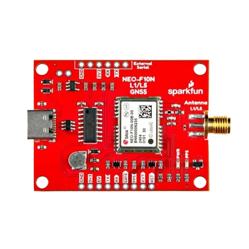
The SparkFun GNSS L1/L5 Breakout - NEO-F10N, SMA (GPS-24114) is a high-precision Global Navigation Satellite System (GNSS) module designed for applications requiring accurate positioning and timing. It features the u-blox NEO-F10N module, which supports dual-band GNSS reception (L1 and L5) for enhanced accuracy and reliability. This breakout board is equipped with an SMA connector for an external antenna, making it suitable for a wide range of applications, including autonomous vehicles, drones, surveying, and IoT devices.

Explore Projects Built with SparkFun GNSS L1/L5 Breakout - NEO-F10N, SMA

Use Cirkit Designer to design, explore, and prototype these projects online. Some projects support real-time simulation. Click "Open Project" to start designing instantly!
Arduino Nano-Based Portable GSM-GPS Navigator with Compass and Stepper Motor Control
Image of Compass: A project utilizing SparkFun GNSS L1/L5 Breakout - NEO-F10N, SMA in a practical application
This circuit features an Arduino Nano microcontroller coordinating communication, navigation, and motion control functions. It includes modules for GSM, GPS, and digital compass capabilities, as well as a stepper motor for precise movement, all powered by a LiPo battery with voltage regulation.
Cirkit Designer LogoOpen Project in Cirkit Designer
Arduino UNO Based Multi-Functional Tracking Device with GPS, GSM, and Wi-Fi Capabilities
Image of Accident Detection: A project utilizing SparkFun GNSS L1/L5 Breakout - NEO-F10N, SMA in a practical application
This circuit features an Arduino UNO as the central microcontroller, interfaced with a GPS NEO 6M module for location tracking, an esp8266 nodemcu for WiFi connectivity, and a SIM900A Mini module for GSM communication capabilities. Additionally, it includes an Adafruit ADXL335 accelerometer for motion sensing, and an LCD display for user interface, whose contrast is controlled by a potentiometer. The Arduino is programmed to coordinate these components, likely for a device that requires location tracking, wireless communication, and motion detection with a user-friendly display.
Cirkit Designer LogoOpen Project in Cirkit Designer
Raspberry Pi 4B-Based GPS and GSM Tracking System with Audio Feedback
Image of unlimited range: A project utilizing SparkFun GNSS L1/L5 Breakout - NEO-F10N, SMA in a practical application
This circuit features a Raspberry Pi 4B as the central processing unit, interfaced with a GPS NEO-6M V2 module for location tracking and an Adafruit FONA 808 Shield for cellular communication. It includes a PAM8406 5V Digital Audio Amplifier connected to an Adafruit STEMMA Speaker for audio output, and a Condenser Microphone connected to the FONA 808 for audio input. Power management is handled by a 12V battery connected to a voltage regulator that steps down the voltage to 5V and 3V required by the various components.
Cirkit Designer LogoOpen Project in Cirkit Designer
Arduino Nano Based GPS Tracker with LoRa Communication and LED Indicator
Image of Sender: A project utilizing SparkFun GNSS L1/L5 Breakout - NEO-F10N, SMA in a practical application
This circuit features an Arduino Nano interfaced with a Neo 6M GPS Module for location tracking and a LORA_RA02 module for long-range communication. The Arduino is powered by a 18650 Li-ion battery through a lipo battery charger module and a step-up boost power converter, ensuring a stable voltage supply. Additionally, the circuit includes a red LED with a current-limiting resistor and a green button, likely for user interaction and status indication.
Cirkit Designer LogoOpen Project in Cirkit Designer

Explore Projects Built with SparkFun GNSS L1/L5 Breakout - NEO-F10N, SMA

Use Cirkit Designer to design, explore, and prototype these projects online. Some projects support real-time simulation. Click "Open Project" to start designing instantly!
Image of Compass: A project utilizing SparkFun GNSS L1/L5 Breakout - NEO-F10N, SMA in a practical application
Arduino Nano-Based Portable GSM-GPS Navigator with Compass and Stepper Motor Control
This circuit features an Arduino Nano microcontroller coordinating communication, navigation, and motion control functions. It includes modules for GSM, GPS, and digital compass capabilities, as well as a stepper motor for precise movement, all powered by a LiPo battery with voltage regulation.
Cirkit Designer LogoOpen Project in Cirkit Designer
Image of Accident Detection: A project utilizing SparkFun GNSS L1/L5 Breakout - NEO-F10N, SMA in a practical application
Arduino UNO Based Multi-Functional Tracking Device with GPS, GSM, and Wi-Fi Capabilities
This circuit features an Arduino UNO as the central microcontroller, interfaced with a GPS NEO 6M module for location tracking, an esp8266 nodemcu for WiFi connectivity, and a SIM900A Mini module for GSM communication capabilities. Additionally, it includes an Adafruit ADXL335 accelerometer for motion sensing, and an LCD display for user interface, whose contrast is controlled by a potentiometer. The Arduino is programmed to coordinate these components, likely for a device that requires location tracking, wireless communication, and motion detection with a user-friendly display.
Cirkit Designer LogoOpen Project in Cirkit Designer
Image of unlimited range: A project utilizing SparkFun GNSS L1/L5 Breakout - NEO-F10N, SMA in a practical application
Raspberry Pi 4B-Based GPS and GSM Tracking System with Audio Feedback
This circuit features a Raspberry Pi 4B as the central processing unit, interfaced with a GPS NEO-6M V2 module for location tracking and an Adafruit FONA 808 Shield for cellular communication. It includes a PAM8406 5V Digital Audio Amplifier connected to an Adafruit STEMMA Speaker for audio output, and a Condenser Microphone connected to the FONA 808 for audio input. Power management is handled by a 12V battery connected to a voltage regulator that steps down the voltage to 5V and 3V required by the various components.
Cirkit Designer LogoOpen Project in Cirkit Designer
Image of Sender: A project utilizing SparkFun GNSS L1/L5 Breakout - NEO-F10N, SMA in a practical application
Arduino Nano Based GPS Tracker with LoRa Communication and LED Indicator
This circuit features an Arduino Nano interfaced with a Neo 6M GPS Module for location tracking and a LORA_RA02 module for long-range communication. The Arduino is powered by a 18650 Li-ion battery through a lipo battery charger module and a step-up boost power converter, ensuring a stable voltage supply. Additionally, the circuit includes a red LED with a current-limiting resistor and a green button, likely for user interaction and status indication.
Cirkit Designer LogoOpen Project in Cirkit Designer

Common Applications

  • High-precision navigation for drones and autonomous vehicles
  • Surveying and mapping
  • Timing synchronization for communication systems
  • IoT devices requiring accurate geolocation
  • Research and development in GNSS technologies

Technical Specifications

Key Technical Details

Parameter Specification
GNSS Module u-blox NEO-F10N
Frequency Bands L1 (1575.42 MHz), L5 (1176.45 MHz)
Positioning Accuracy Down to 0.3 meters (with RTK corrections)
Update Rate Up to 10 Hz
Input Voltage 3.3V (regulated)
Power Consumption ~30 mA (typical)
Antenna Connector SMA (external antenna required)
Communication Interfaces UART, I2C
Operating Temperature -40°C to +85°C
Dimensions 25.4 mm x 25.4 mm

Pin Configuration and Descriptions

Pin Name Pin Number Description
GND 1 Ground connection
3.3V 2 Power supply input (3.3V regulated)
TX 3 UART Transmit (data output from the module)
RX 4 UART Receive (data input to the module)
SDA 5 I2C Data Line
SCL 6 I2C Clock Line
PPS 7 Pulse Per Second output for timing applications
RST 8 Reset pin (active low)

Usage Instructions

How to Use the Component in a Circuit

  1. Power Supply: Connect the 3.3V pin to a regulated 3.3V power source and the GND pin to the ground.
  2. Antenna Connection: Attach an external GNSS antenna to the SMA connector for optimal signal reception.
  3. Communication Interface:
    • For UART communication, connect the TX and RX pins to the corresponding UART pins on your microcontroller.
    • For I2C communication, connect the SDA and SCL pins to the I2C bus of your microcontroller.
  4. Optional Connections:
    • Use the PPS pin for precise timing applications.
    • Connect the RST pin to a GPIO pin on your microcontroller for manual resets if needed.

Important Considerations and Best Practices

  • Antenna Placement: Ensure the external antenna has a clear view of the sky for optimal satellite reception.
  • Power Supply: Use a clean and stable 3.3V power source to avoid noise and interference.
  • UART/I2C Selection: Configure your microcontroller to use the appropriate communication protocol.
  • RTK Corrections: For high-precision applications, use Real-Time Kinematic (RTK) corrections with a compatible base station.

Example Code for Arduino UNO

Below is an example of how to interface the SparkFun GNSS L1/L5 Breakout with an Arduino UNO using UART communication:

#include <SoftwareSerial.h>

// Define RX and TX pins for SoftwareSerial
SoftwareSerial mySerial(4, 3); // RX = Pin 4, TX = Pin 3

void setup() {
  Serial.begin(9600); // Initialize hardware serial for debugging
  mySerial.begin(9600); // Initialize software serial for GNSS module

  Serial.println("SparkFun GNSS L1/L5 Breakout Example");
}

void loop() {
  // Check if data is available from the GNSS module
  if (mySerial.available()) {
    // Read and print GNSS data to the Serial Monitor
    while (mySerial.available()) {
      char c = mySerial.read();
      Serial.print(c);
    }
  }
}

Note: Ensure the GNSS module's baud rate matches the mySerial.begin() value (default is 9600).

Troubleshooting and FAQs

Common Issues and Solutions

  1. No GNSS Fix:

    • Ensure the external antenna is properly connected and has a clear view of the sky.
    • Check the power supply for stability and correct voltage.
    • Verify the module's configuration and communication settings.
  2. No Data Output:

    • Confirm the TX and RX connections between the GNSS module and the microcontroller.
    • Ensure the baud rate in your code matches the module's default baud rate (9600).
  3. Intermittent Signal Loss:

    • Avoid placing the antenna near sources of interference, such as Wi-Fi routers or metal objects.
    • Use a high-quality GNSS antenna for better performance.

FAQs

Q: Can I use this module indoors?
A: While the module may work indoors near windows, optimal performance requires a clear view of the sky.

Q: What type of antenna should I use?
A: Use an active GNSS antenna with an SMA connector for best results.

Q: How do I enable RTK corrections?
A: RTK corrections require additional hardware (e.g., a base station) and configuration. Refer to the u-blox NEO-F10N datasheet for detailed instructions.

Q: Can I power the module with 5V?
A: No, the module requires a regulated 3.3V power supply. Use a voltage regulator if your system operates at 5V.